Method of forming bright metallized film laminate

a technology of metallized film and bright color, applied in the field of bright metallized film laminate, can solve the problems of shortening the processing time associated with metallizing three-dimensional articles, disadvantageous depositing of metal directly onto articles only after the article has been formed, and customized applications, etc., to achieve superior optical and deformation properties

Inactive Publication Date: 2001-12-13
SOLIANT
View PDF0 Cites 9 Cited by
  • Summary
  • Abstract
  • Description
  • Claims
  • Application Information

AI Technical Summary

Benefits of technology

[0013] Therefore, it is an object of the present invention to provide a bright metallized film laminate having superior optical and deformation properties, and a method of making such film laminates.
[0014] In its broadest form, the invention comprises a metallized formable laminate made of a discontinuous layer of indium islands deposited on a microscopically smooth film formed of an alloy containing polyvinylidene difluoride (PVDF) and an acrylate polymer. In the preferred embodiments the film is the FLUOREX.RTM.-brand fluoropolymer (Rexam, Inc., Matthews, N.C.) in which the polyvinylidene difluoride film includes about 25 percent acrylic component. This indium-FLUOREX.RTM. combination has superior, quantifiable optical and deformation properties as compared to other bright, formable films.
[0015] In another aspect, the invention includes an adhesive layer placed on the surface of the discontinuous indium layer opposite the PVDF-acrylate (or "acrylic") film. A thermoplastic layer is then placed on the adhesive. Such a thermoplastic layer may be comprised of polyvinyl chloride (PVC), thermoplastic olefin (TPO), polycarbonates (PC), or acrylonitrile-butadiene-styrene (ABS) copolymer. The adhesive layer prevents the undesirable formation of indium oxide (In.sub.2O.sub.3), a whitish, unreflective compound. Moreover, when the thermoplastic layer includes polyvinyl chloride, the adhesive layer helps to prevent chloride ion or hydrochloric acid from reacting with the indium layer to form indium trichloride (InCl.sub.3), an unreflective compound.

Problems solved by technology

This necessitates drying time for each application, which lengthens the processing times associated with metallizing three-dimensional articles.
Therefore, depositing metal directly onto an article only after the article has been formed can be disadvantageous.
Such laminates also facilitate customized application, limited only by adhesive effectiveness.
Moreover, using a metallized film laminate reduces chemical compatibility problems that can arise between the metal and the polymeric substrate when metallizing articles in-situ.
Using such metallized film laminates, though convenient, can result in an inferior finish as compared to that obtained by in-situ techniques.
Such formable film laminates have poor flexibility, however, often cracking when the metallized substrates are excessively deformed.
Moreover, such moldable films tend to lose luster over time.
This is particularly pernicious with respect to metallized indium layers, which in the presence of halogen-containing polymers (e.g., polyvinyl chloride, "PVC") can undergo an oxidation-reduction reaction that converts elemental indium to indium trichloride.
Finally, to the extent such moldable films are formed from continuous metallized layers, corrosion problems result.

Method used


Image

  • Method of forming bright metallized film laminate
  • Method of forming bright metallized film laminate
  • Method of forming bright metallized film laminate

Examples


example 2

[0069] The method can include the following steps: casting an acrylic primer layer (TEDLAR 68070 from DuPont) at a dry thickness of 0.5 mil on FLUOREX.RTM. A; casting a polyurethane layer (SU 6729 from Stahl) at a dry thickness of 0.5 mil on the dried primer layer; depositing a layer of indium at an OD of 1.15 on the polyurethane surface through vacuum deposition; making an adhesive composite by casting an acrylic material (ELVACITE 2009) at a dry thickness of 0.5 mil on a 2 mil PET; casting a polyurethane (ADH 222 from Novacote) at a dry thickness of 0.5 mil on dried ELVACITE 2009; adding a PET film to the indium surface and press polishing; removing the PET from the indium surface and bonding the ADH 222 surface of the adhesive composite onto the indium surface; removing the PET from the adhesive composite; bonding the composite to a 20 mil ABS through a hot nip at between 330.degree. to 380.degree. F.

[0070] The preferred embodiments of the invention and the method of making them ...

first embodiment

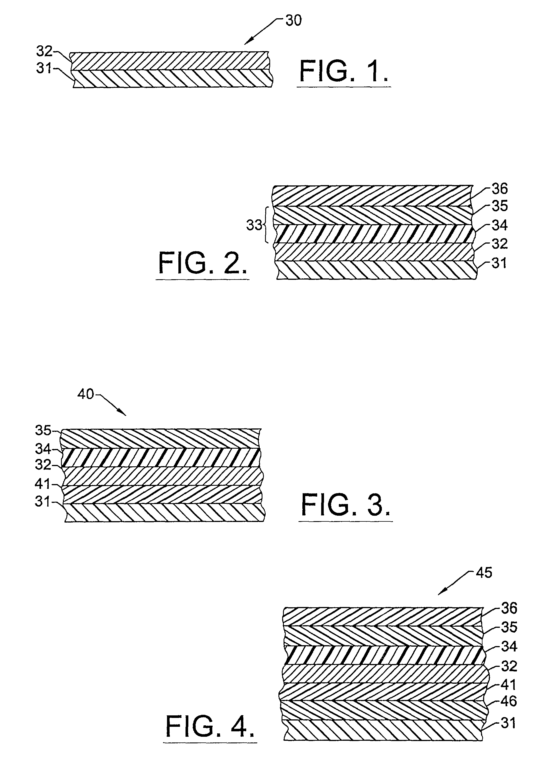
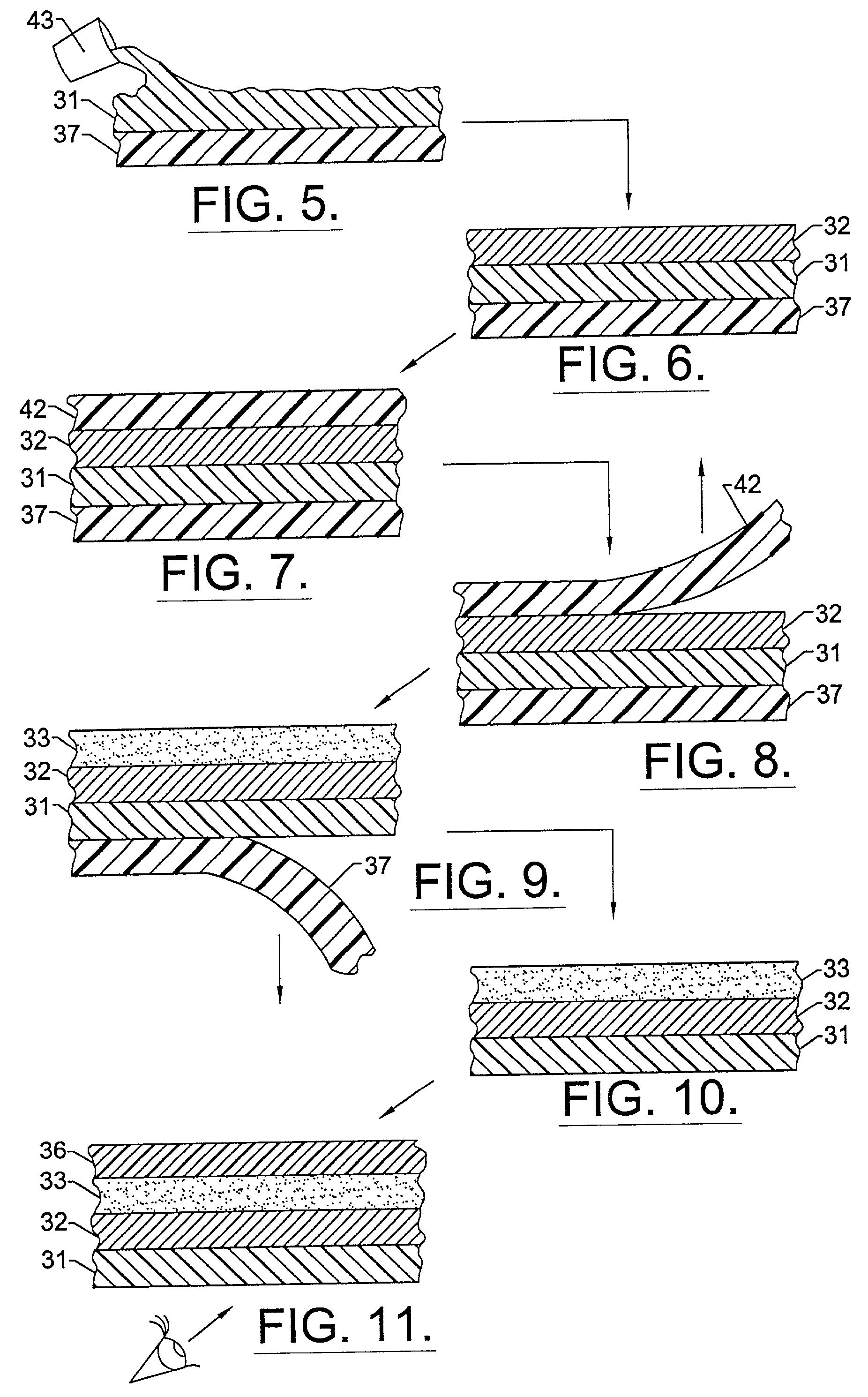
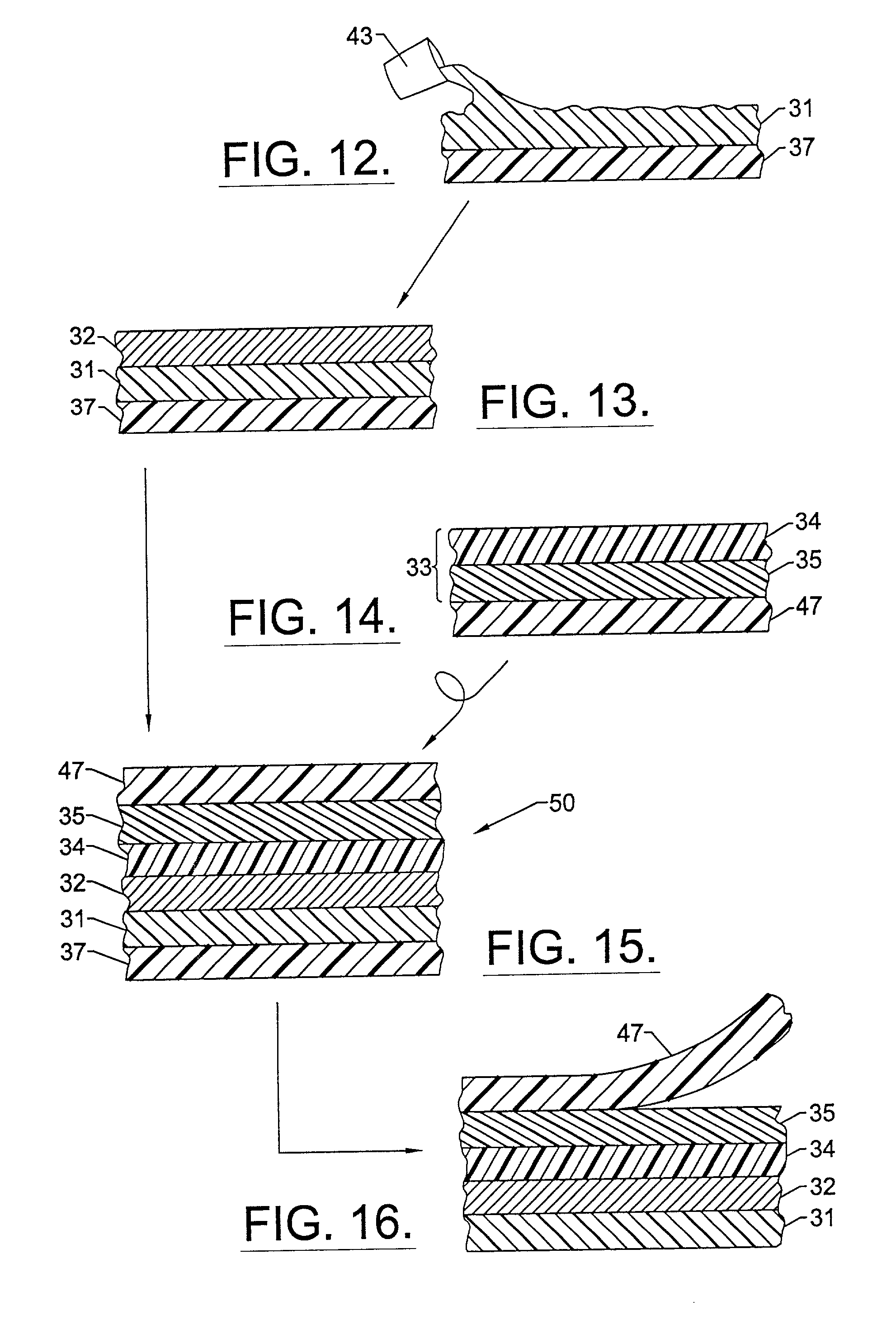
[0075] FIGS. 5-11 illustrate a method of making the invention. Where possible, the respective layers will carry the same reference numerals as in the previous drawings. Accordingly, FIG. 5 shows that in a first step, the PVDF-acrylic composition is cast onto the layer 31 from an appropriate casting source schematically illustrated at 43, onto a polyester substrate 37. Suitable casting methods include a knife-over roll coating process, a reverse roll coating process, or preferably a slot die coating process. The discontinuous layer of indium islands 32 is then added to the PVDF-acrylic layer 31 resulting in the structure illustrated in FIG. 6. In the next step, a second polyester layer 42 is added for the purpose of press polishing the indium layer 32 in the manner described previously. FIG. 8 illustrates that this polyester layer 42 is then removed leaving the smooth surface of the indium layer 32 behind.

[0076] FIG. 9 illustrates the next two steps in which the original polyester la...


PUM

PropertyMeasurementUnit
thicknessaaaaaaaaaa
thicknessaaaaaaaaaa
thicknessaaaaaaaaaa

Abstract

Disclosed is a method for forming a bright metallized laminate. In one aspect, the method includes press polishing a polyvinylidene difluoride-containing film, either before or after the deposition of a discontinuous layer of indium islands, so that the polyvinylidene difluoride-containing film becomes microscopically smooth. In another aspect, the method includes applying a thermoplastic leveling layer to a polyvinylidene difluoride-containing film and thereafter depositing a discontinuous layer of indium islands upon the thermoplastic leveling layer.

Description

[0001] This application is a divisional application of copending U.S. application Ser. No. 09 / 268,085, filed Mar. 12, 1999, which is hereby incorporated herein by reference.[0002] The invention relates to bright film technology. In particular, the invention is a bright metallized film laminate that has superior optical and deformation properties. In a preferred embodiment, the film laminate includes a layer of discontinuous indium islands deposited on a polyvinylidene difluoride-acrylic alloy film. The invention is also an improved method of making bright metallized film laminates.[0003] Metallized polymeric finishes can be used to complement and even replace bright, reflective metal surface treatments, particularly chrome plating. Polymeric structures having metallized finishes are commonly used as substitutes for articles, such as automobile grills, that are expected to have a chrome-plated appearance. Decorative polymeric components, in fact, are becoming standard in the automobi...

Claims


Application Information

Patent Timeline
Patent Type & Authority Applications(United States)
IPC IPC(8): B32B15/08B32B15/082
CPCB32B15/08Y10T428/31Y10T428/24917Y10T428/31855Y10T428/31551Y10T428/3154Y10T428/31678B32B15/082B32B27/304B32B2307/406B32B7/12B32B2255/10B32B2255/205B32B2327/00
Inventor FIELDS, THOMAS R.SMITH, DONSONG, QUANOUTLAW, MARK O.DICK, KENNETH W.
Owner SOLIANT
Why Eureka
Try Eureka