
Method and apparatus for producing a plasma display

a plasma display and plasma technology, applied in the manufacture of electric discharge tubes/lamps, liquid/solution decomposition chemical coatings, electromechanical systems, etc., can solve the problems of difficult formation of phosphor layers, low accuracy, and high cos

Inactive Publication Date: 2002-01-24
PANASONIC CORP +1
View PDF8 Cites 119 Cited by
  • Summary
  • Abstract
  • Description
  • Claims
  • Application Information

AI Technical Summary

Benefits of technology

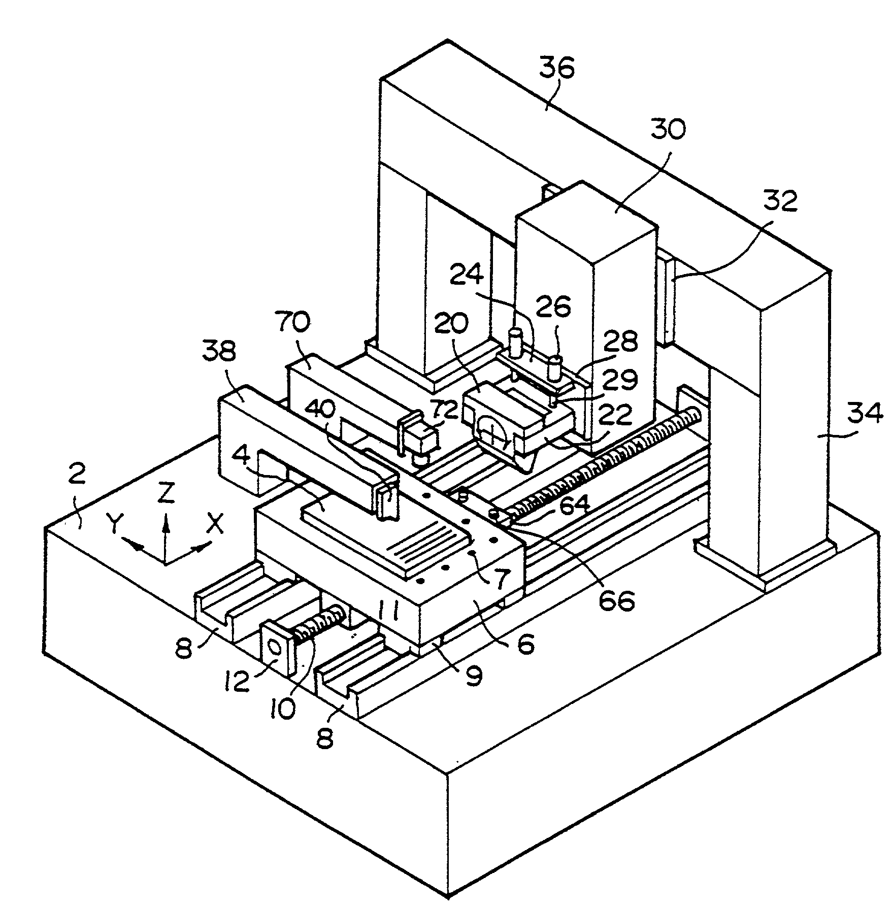
[0013] Another object of the present invention is to provide an apparatus for producing the above high quality plasma display continuously at a high productivity level.

Problems solved by technology

However, the methods of using screen printing have a disadvantage that since the screen is changed in form by repeated printing, the accuracy is low, making it difficult to form a phosphor layer capable of providing a highly precise plasma display, and also have a problem that the cost is high since the expensive screen must be frequently exchanged.
However, in this method, since layers of the respective phosphors of red (R), green (G) and blue (B) are formed, the complicated process of coating, exposure, development, drying, etc. must be repeated three times for R, G and B. The method also has a disadvantage that phosphor pastes are greatly lost, to raise the cost.
So, since the amount of the phosphor powder in the paste cannot be increased, the thickness of the phosphor layer cannot be controlled advantageously.
Furthermore, this method also has such a problem that the ink jet nozzle is clogged by the phosphor powder and cannot be practically used.

Method used


Image

  • Method and apparatus for producing a plasma display
  • Method and apparatus for producing a plasma display
  • Method and apparatus for producing a plasma display

Examples


example 1

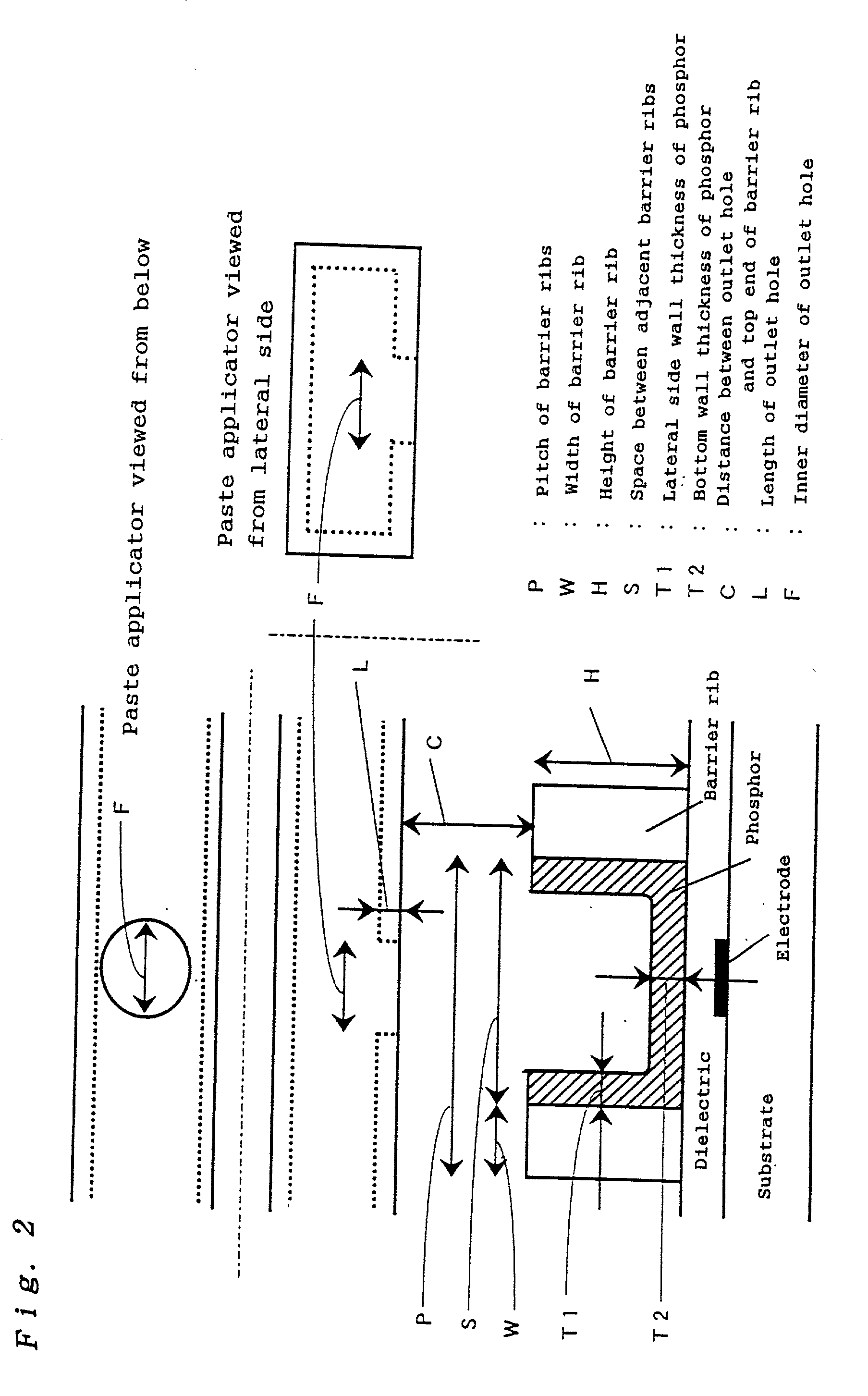
[0293] A 340 mm wide.times.440 mm deep.times.2.8 mm thick soda glass substrate fully screen-printed with a photosensitive silver paste with a thickness of 5 .mu.m was exposed using a photo mask, developed and burned, to form 1920 silver electrodes as stripes at a pitch of 220 .mu.m. A glass paste consisting of a glass and a binder was screen-printed over the electrodes on the substrate, and burned to form a dielectric layer. Subsequently, a photosensitive glass paste consisting of a glass powder and a photosensitive organic component was further screen-printed, with a thickness of 200 .mu.m, and dried. Then, a photo mask designed to form barrier ribs between the respectively adjacent electrodes was used for exposure, and development and burning were effected, to form barrier ribs. Thus, 1921 barrier ribs with a width of 30 .mu.m and a height of 130 .mu.m were formed at a pitch of 220 .mu.m.

[0294] The glass substrate with barrier ribs formed like this was coated with the phosphor pas...

example 2

[0311] A phosphor layer was formed as described in Example 1, except that two paste applicators were used instead of one paste applicator and moved at 50 mm / sec. The evaluation results are shown in Table 1.

example 3

[0312] A phosphor layer was formed as described in Example 1, except that three paste applicators respectively filled with any of the red, green and blue phosphor pastes were used instead of one paste applicator, for coating. The evaluation results are shown in Table 1.


PUM

PropertyMeasurementUnit
diameteraaaaaaaaaa
distanceaaaaaaaaaa
distanceaaaaaaaaaa

Abstract

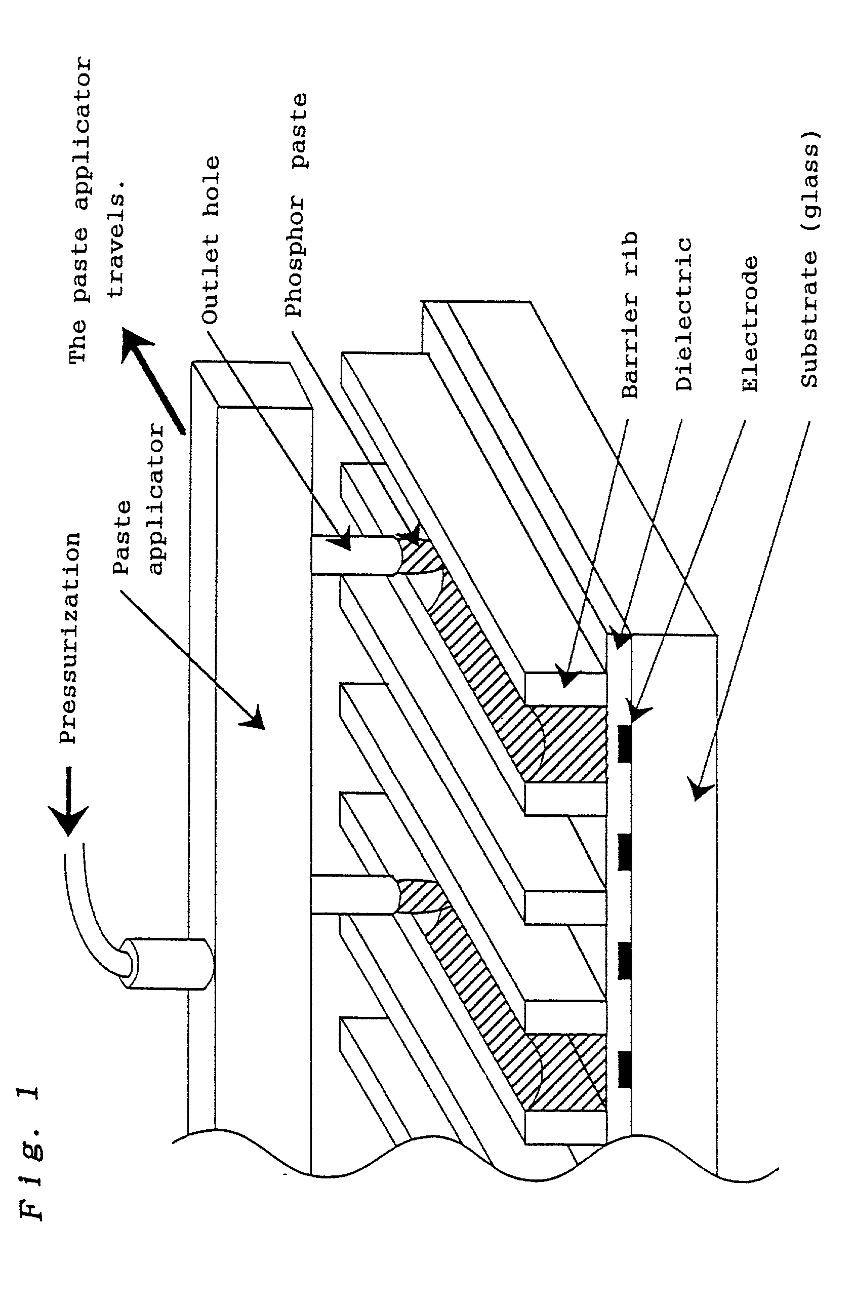
Since a widely applicable high quality plasma display equipped with a phosphor layer suitable as a highly precise plasma display can be produced continuously at a high productivity level, an industrially advantageous method and apparatus for producing a plasma display can be provided. The highly precise plasma display obtained in the present invention can be widely used in the display field, for example, for wall mounted television sets, information displays, etc. The method for producing a plasma display of the present invention comprises the step of continuously applying a phosphor paste containing a phosphor powder and an organic compound onto a substrate with a plurality of barrier ribs from a paste applicator with a plurality of outlet holes. Furthermore, the present invention comprises the steps of coating a substrate with a plurality of barrier ribs, with three phosphor pastes respectively containing a phosphor powder emitting light of red, green or blue, as stripes in the spaces between the respectively adjacent barrier ribs on the substrate, from a paste applicator with outlet holes, and heating to form a phosphor layer. Moreover, the apparatus for producing a plasma display of the present invention comprises a table for fixing a substrate with a plurality of barrier ribs, a paste applicator with a plurality of outlet holes to face the barrier ribs of the substrate, a supply means for supplying a phosphor paste to the paste applicator, and a moving means for three-dimensionally moving the table and the paste applicator relatively each other.

Description

[0001] The present invention relates to a method and apparatus for producing a new plasma display suitably used for wall mounted television sets, information displays, etc.[0002] In recent years, with the progress of multimedia, displays for displaying diverse kinds of information play more important roles. In this connection, the displays are required to be larger and thinner, and liquid crystal displays are being used in many fields including notebook type personal computers. However, it is difficult to use liquid crystal displays for large television sets in view of price and response speed. So, as the most promising type of large displays, plasma displays attract attention.[0003] The present invention relates to a means for providing a plasma display capable of forming a phosphor layer usable as a highly precise plasma display in this field.PRIOR ARTS[0004] A plasma display has electric discharge caused in discharge spaces formed between a front glass substrate and a rear glass ...

Claims


Application Information

Patent Timeline
Patent Type & Authority Applications(United States)
IPC IPC(8): H01J9/227
CPCH01J9/227H01J2211/42
Inventor IGUCHI, YUICHIROMATSUMOTO, MASAHIROMIKAMI, YUKOMASAKI, TAKAKISANO, TAKAOKITAMURA, YOSHIYUKITANI, YOSHINORIIKEUCHI, HIDEKI
Owner PANASONIC CORP
Learn More