

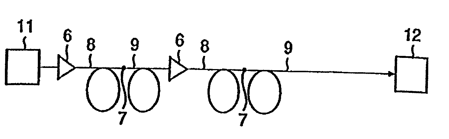
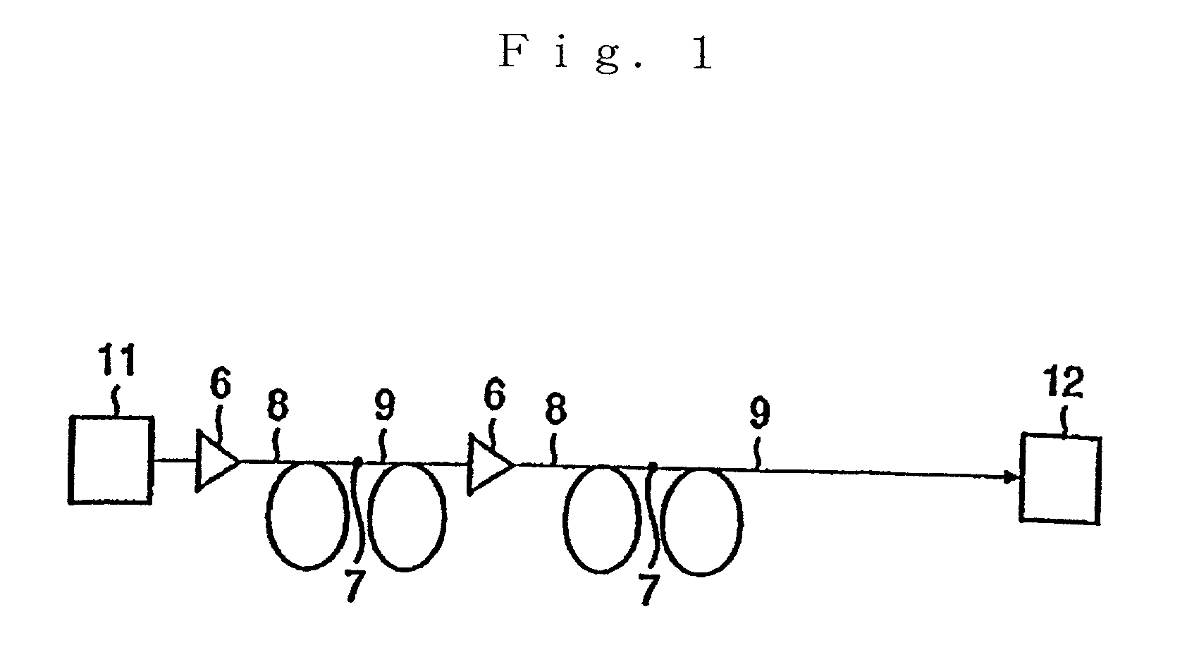
Optical transmission line
a transmission line and optical technology, applied in the field of optical transmission lines, can solve the problems of non-linearity phenomenon, difficult long distance optical communication, and inability to utilize conventional optical amplifiers, and achieve excellent effects, optimize the refractive index profile of the first, and ensure the control of waveform distortion resulting from non-linearity phenomenon
- Summary
- Abstract
- Description
- Claims
- Application Information
AI Technical Summary
Benefits of technology
Problems solved by technology
Method used
Image

Examples
Embodiment Construction
-0.5 0.75 0.50 6.20 6.64 0.067 81.5 1228 8.5 Example 2 -0.4 0.70 0.45 6.10 9.41 0.069 82.3 1346 6.0
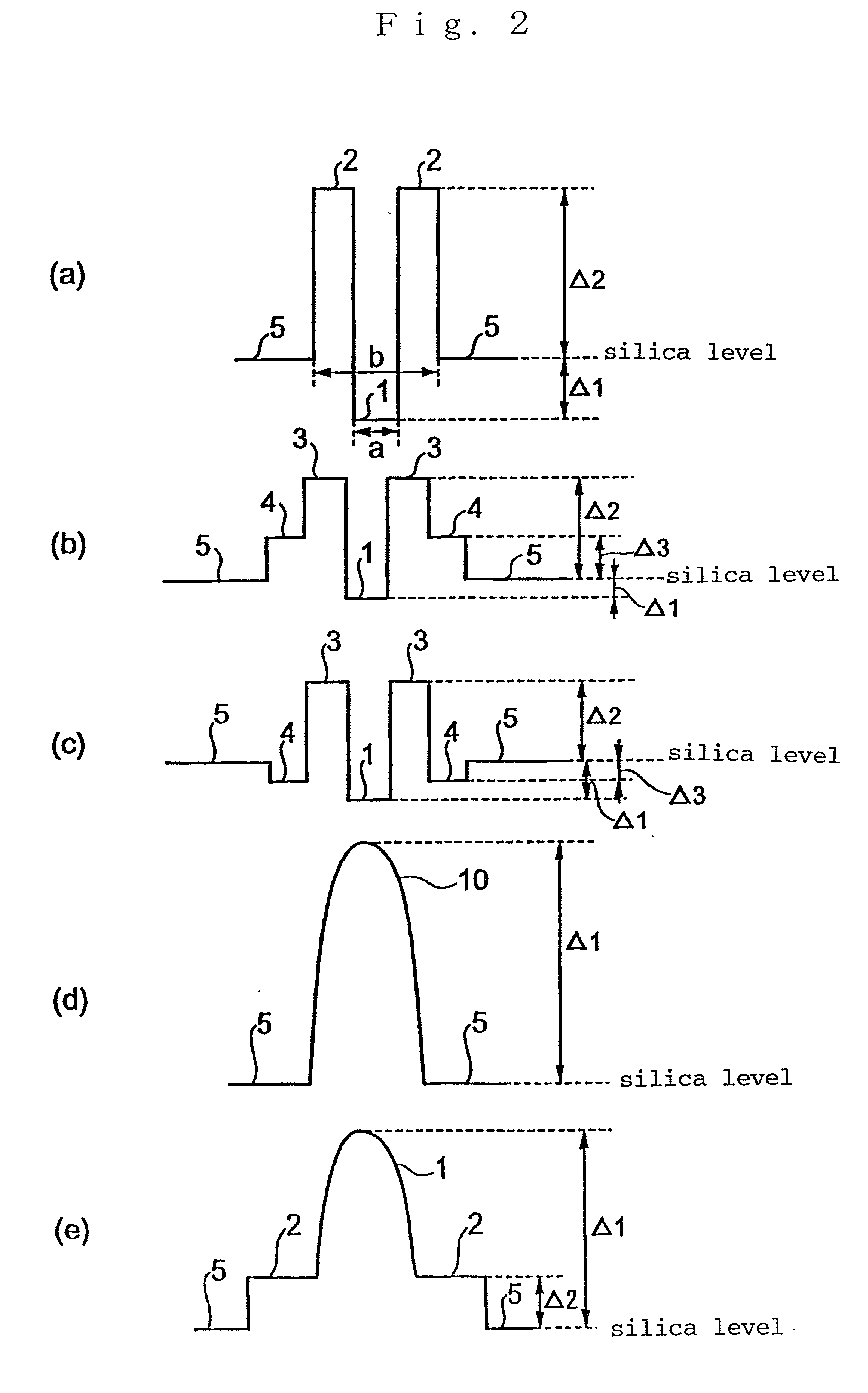
[0087] Each of the relative refractive index differences .DELTA.1 and .DELTA.2 are defined by the following equations (3) and (4) when the refractive index of the vacuum is 1, the relative refractive index of the center core is n1, the relative refractive index of the side core 2 is n2 and the relative refractive index of the cladding 5 is nc, of which the unit is %.
.DELTA.1=[{(n1).sup.2-(nc).sup.2} / 2(n1).sup.2].times.100 (3)
.DELTA.2=[{(n2).sup.2-(nc).sup.2} / 2(n2).sup.2].times.100 (4)
[0088] As is clear from Table 1, the effective core section area is 80 .mu.m.sup.2 or more in either optical fiber in Examples 1 and 2. That is to say, it can be confirmed that in the optical fibers of Examples 1 and 2, the effective core section area which is the same or more of the effective core section area of a conventional single mode optical fiber is gained. Here, the slope in Table 1 is a dispersio...
PUM
 Abstract
Description
Claims
Application Information