Double capacitor

a technology of double capacitors and capacitors, applied in the direction of transit tube circuit elements, transit tube leading-in arrangements, gas-filled discharge tubes, etc., can solve the problems of detrimental effect of amplified signals

Inactive Publication Date: 2002-02-07
E2V TECH (UK) LTD
View PDF0 Cites 1 Cited by
  • Summary
  • Abstract
  • Description
  • Claims
  • Application Information

AI Technical Summary

Problems solved by technology

In tubes of this type, RF energy from the region around the electron gun may caus...

Method used


Image

  • Double capacitor
  • Double capacitor
  • Double capacitor

Examples


Embodiment Construction

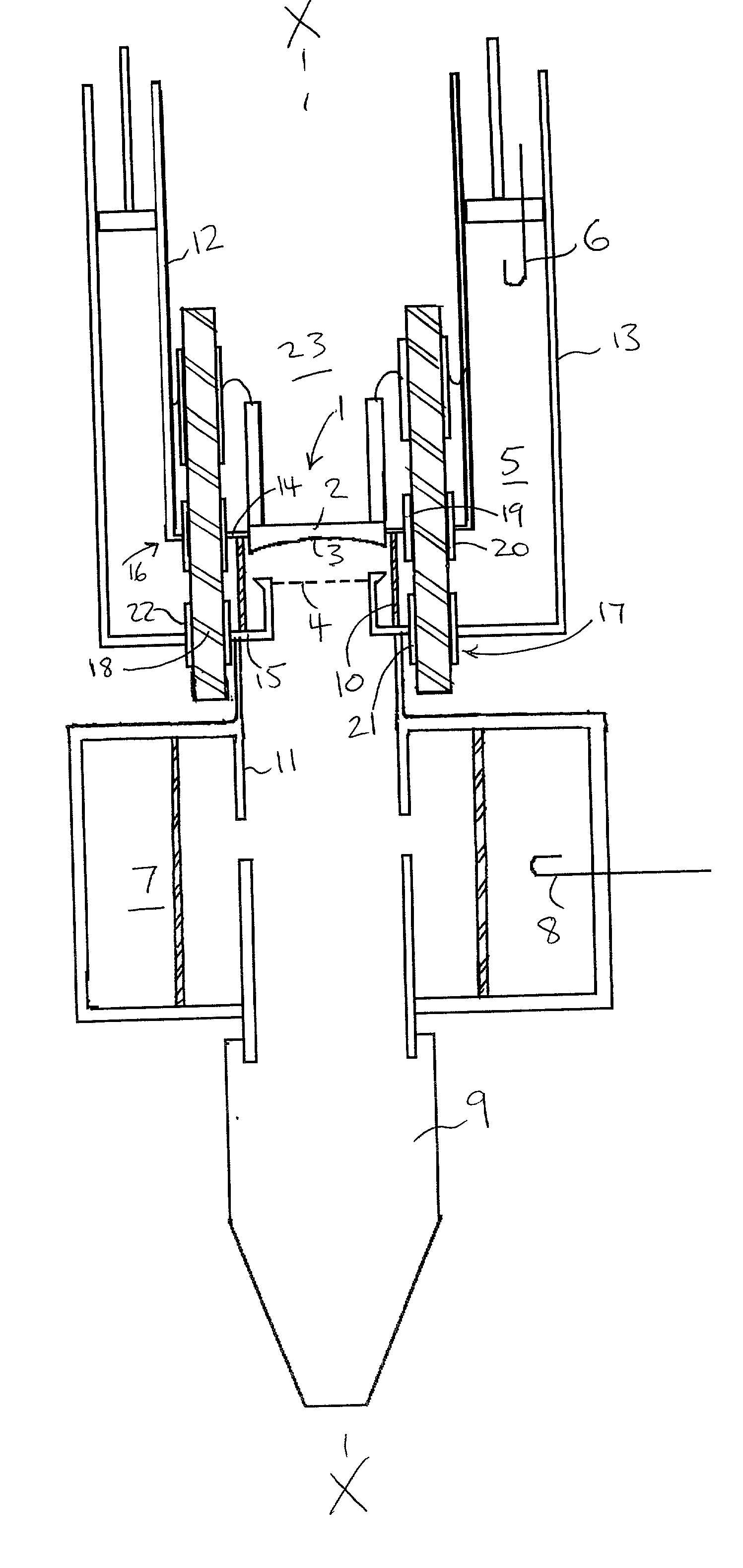
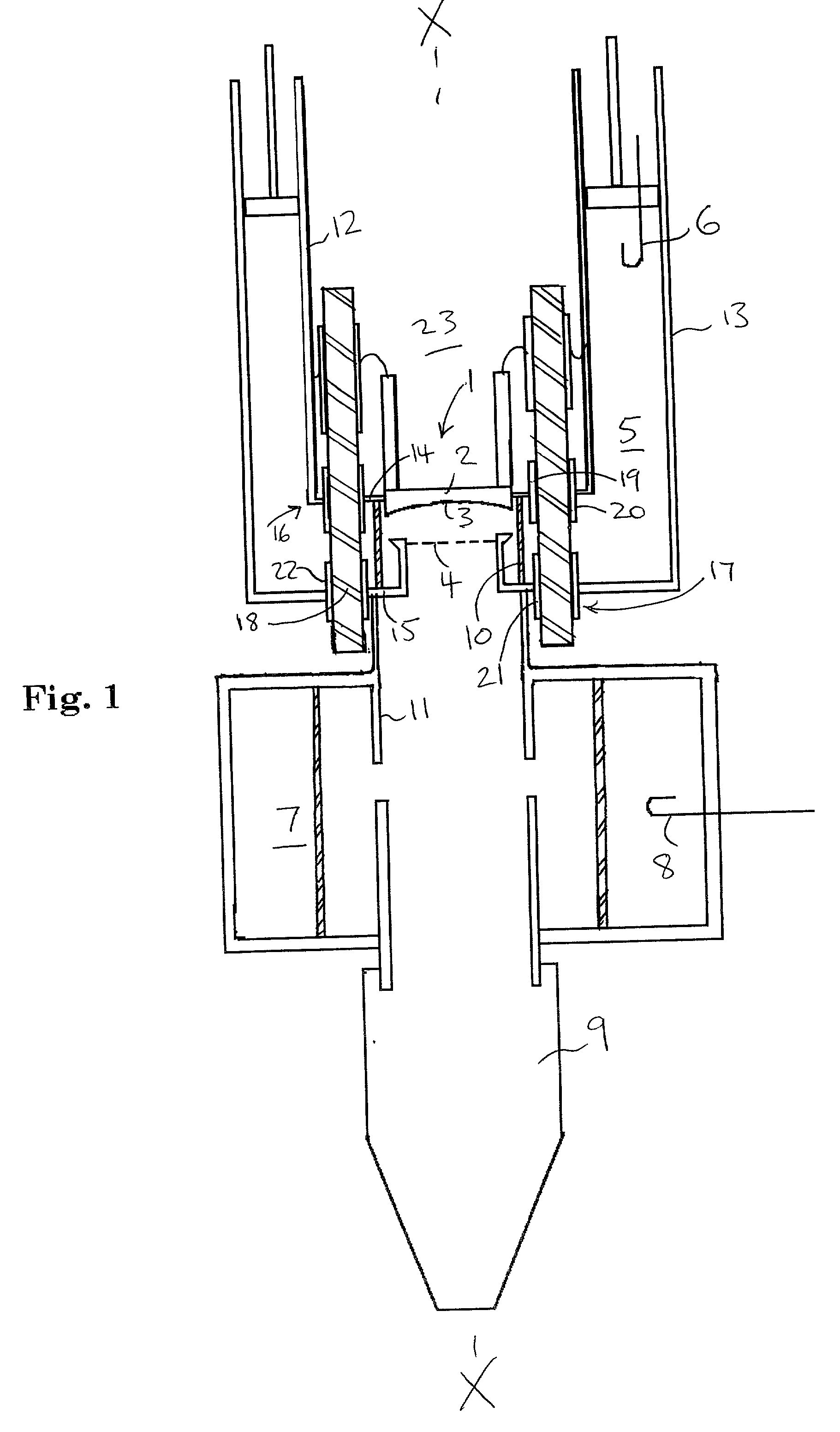
[0017] With reference to FIG. 1, an IOT amplifier includes an electron beam tube with an electron gun 1 having a cathode 2 with a concave front surface 3 from which, in use, electrons are emitted. A grid 4 is located in front of the cathode 2.

[0018] A high frequency resonant input cavity 5 is of annular cross-section and is arranged coaxially about the electron gun 1 around the longitudinal axis X-X of the arrangement. A high frequency signal to be amplified is applied to the input cavity 5 via a coupling loop 6. This causes modulation of the electron beam in the cathode / grid space. The modulated electron beam is transmitted along the axis X-X to an output cavity 7 from which an amplified RF signal is extracted via a coupling loop 8. The spent electrons of the beam are then intercepted at a collector 9.

[0019] The region in which the electron beams are generated and transmitted is surrounded by a vacuum envelope which, in this schematic diagram, is partially defined by ceramic suppor...


PUM


Abstract

In an electron beam tube arrangement, such as an IOT amplifier, an input cavity surrounds an electron gun. The cavity includes parts which are at high and low relative electrical potentials. These are separated by RF chokes to provide dc isolation whilst acting as a short circuit to high frequency radiation coupled into the cavity. The arrangement also includes a bypass capacitor located behind the electron gun which short circuits stray or leakage radiation to prevent deterioration of the amplified signal. The bypass capacitor presents a distributed capacitance of low inductance. In one embodiment, the RF choke and bypass capacitor include insulating material defined by a common member on which metallization layers are deposited.

Description

[0001] This invention relates to electron beam tubes and more particularly to tubes in which stray or leakage high frequency energy is reduced or eliminated.BACKGROUND TO THE INVENTION[0002] In an inductive output tube (IOT), a high frequency signal to be amplified is applied to an input cavity surrounding the electron gun to modulate the density of the electron beam generated by the electron gun. The modulated electron beam is then passed via a drift tube to an output cavity from which an amplified high frequency signal is coupled. In tubes of this type, RF energy from the region around the electron gun may cause undesirable oscillations which can have a detrimental effect on the amplified signal.[0003] According to the invention, there is provided an electron beam tube comprising an electron gun; and capacitor means which provides an RF choke capacitor between parts of a high frequency input cavity at different electrical potentials and which also provides a distributed bypass cap...

Claims


Application Information

Patent Timeline
IPC IPC(8): H01J23/15H01J11/00H01J23/16H01J23/54H01J25/04H01J31/00
CPCH01J23/15H01J23/54H01J25/04
Inventor BARDELL, STEVENCLAYWORTH, GEOFFREY THOMAS
Owner E2V TECH (UK) LTD
Why Eureka
Try Eureka