Co-combustion of waste sludge in municipal waste combustors and other furnaces

a technology of municipal waste and combustion furnace, which is applied in the direction of solid fuel combustion, combustion types, lighting and heating apparatus, etc., can solve the problems of poor combustion, extremely adverse air emissions, and high cost and even dangerous technology

Inactive Publication Date: 2002-05-02
ECO TECH LLC
View PDF0 Cites 14 Cited by
  • Summary
  • Abstract
  • Description
  • Claims
  • Application Information

AI Technical Summary

Problems solved by technology

However, most of those installations experienced poor combustion and produced extremely adverse air emissions.
However, this technology was expensive and even dangerous, because of potential health hazards related to inhalation of fugitive dust and dust explosions.
These approaches failed to achieve commercial acceptance of their technologies because of limited applicability, economic disadvantages or technological disadvantages.
Additionally, conventional approaches did not address the problems of controlling odor in the handling and transporting of sludge prior to introduction into a furnace.
However, operating costs of such a system are high and the rotary centrifugal atomizer disclosed is difficult to reliably maintain because of plugging and wear.
The rotary atomizer discharges a significant fraction of large particles that do not burn completely, and deposition of material on boiler internals becomes a problem.
However, this requires expensive construction of an oxygen-producing plant adjacent to an owner's core production facilities or purchase of large quantities of bottled oxygen.
However, this device does not involve sludge, and it is not designed for atomizing particles to burn in suspension.
Previous systems were not...

Method used


Image

  • Co-combustion of waste sludge in municipal waste combustors and other furnaces
  • Co-combustion of waste sludge in municipal waste combustors and other furnaces
  • Co-combustion of waste sludge in municipal waste combustors and other furnaces

Examples


Embodiment Construction

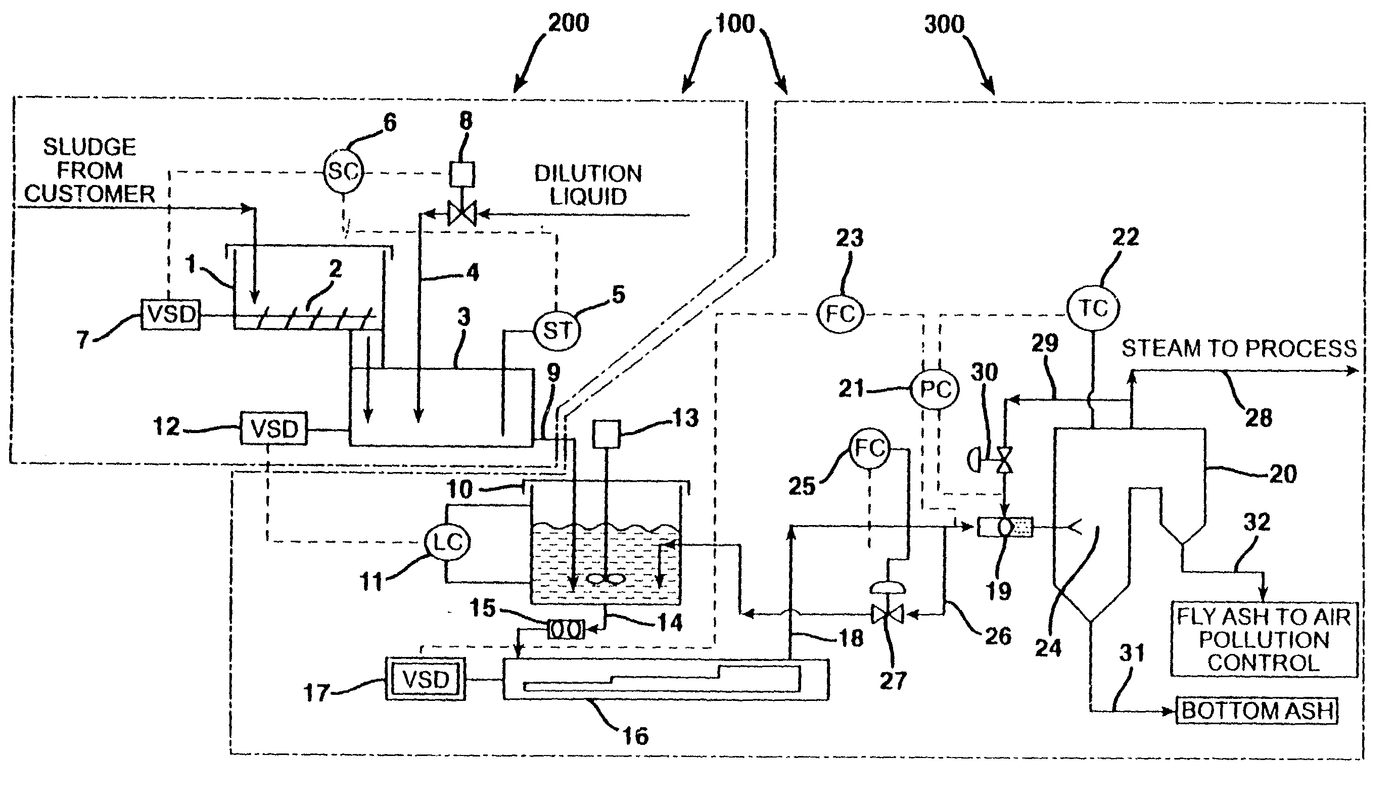
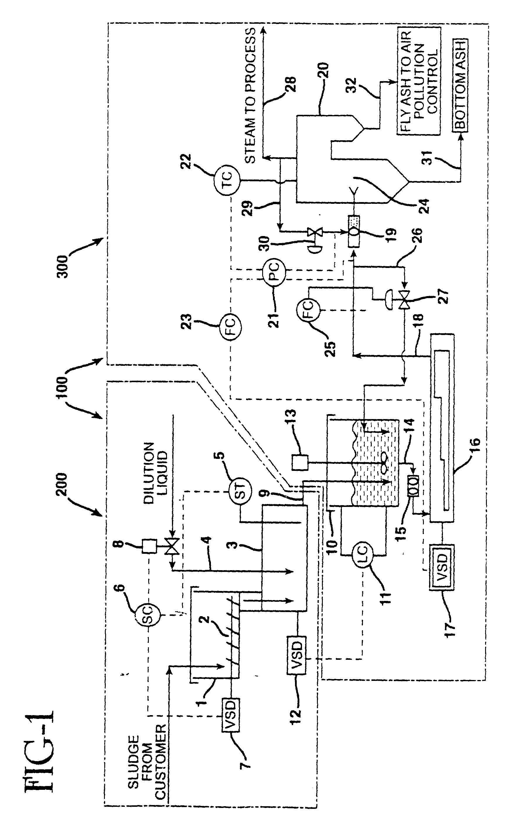
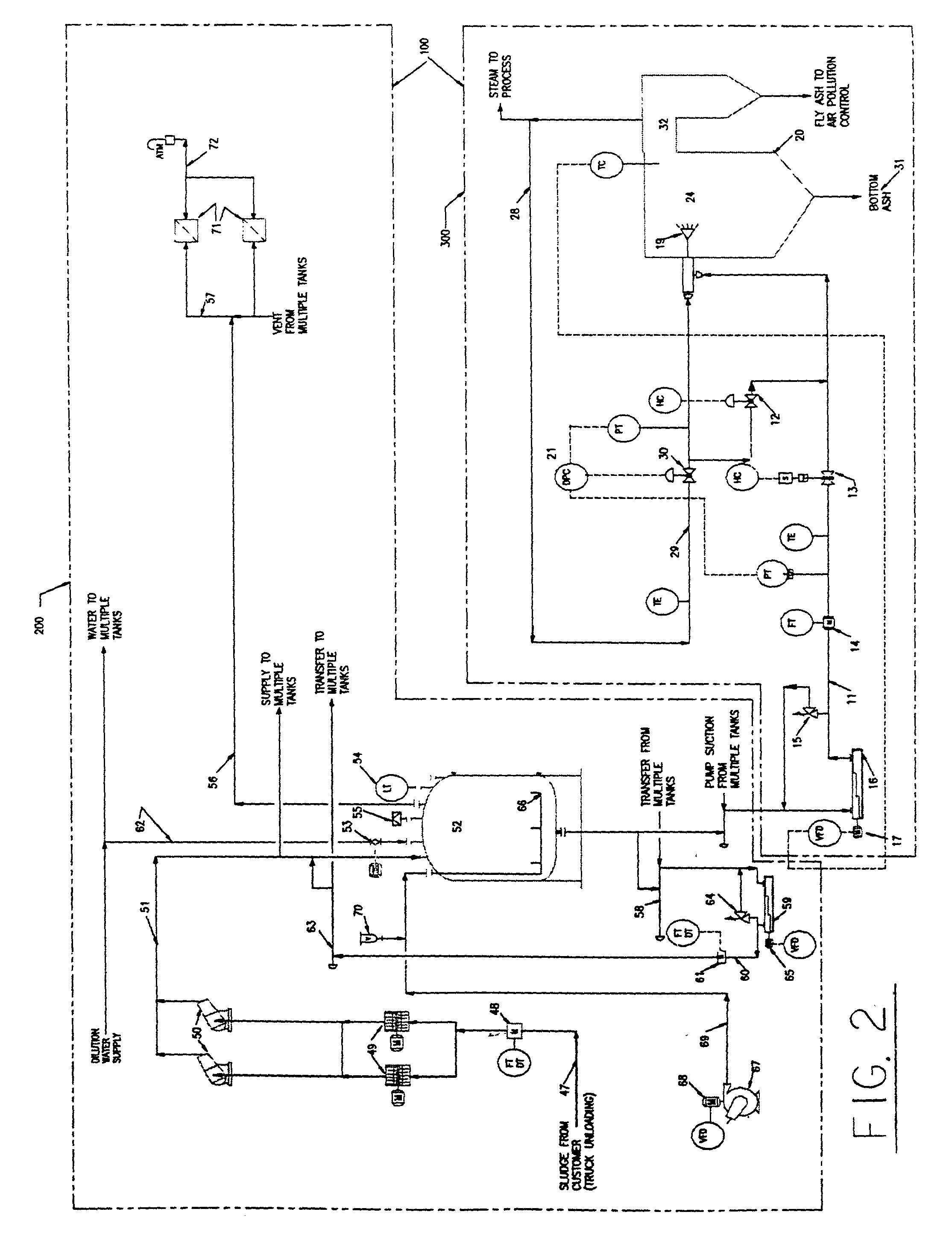
[0060] A system according to the present invention was tested in which diluted paper and sewage sludge were injected into an operating conventional municipal waste combustor.

[0061] The combustor facility selected for testing has three mass burn refractory MWC's, each rated at 120 tons per day. Normal operation is with two combustors operating and one on stand-by. The combustors are tied to two waste heat boilers and associated air pollution control trains. Each air pollution control train consists of an electrostatic precipitator and spray absorber. The selected facility is permitted to burn up to 240 tons per day of municipal solid waste (MSW) and generates for sale up to 60,000 pounds per hour of super-heated steam at 230 psig and 500.degree. F.

[0062] Minor modifications were made to the existing combustor facility to allow for receiving, diluting, mixing, storage and pumping of sludge. A plastic mixing tank having a capacity of 1800 gallons was installed at the facility and a Nem...


PUM


Abstract

A system and method for treating, injecting and co-combusting sludge in a municipal waste or other solid fuel combustor. The system includes a sludge receiving and treatment module and a sludge injection and combustion module. The sludge is received and stored in one or more storage hoppers where its moisture content is monitored and varied to obtain a sludge having a desired moisture content. The treated sludge is then pumped to a furnace injection nozzle where it is preferably atomized with steam and sprayed into the combustion zone of the furnace. Improved odor control in sludge handling is also provided by a storage tank and a sludge tanker trailer each having an air diffuser for mixing and aerating the sludge and a filter system for filtering odors.

Description

[0001] CROSS-REFERENCE TO RELATED APPLICATIONS[0002] This application is a Continuation-in-Part of U.S. Application No. 09 / 420,291, filed Oct. 18, 1999, which claims the benefit of U.S. Provisional Application No. 60 / 104,806, filed Oct. 19,1998.[0003] 1. Field of the Invention[0004] This invention pertains to municipal solid waste combustors (MWCs) and, by extension, to all solid fuel steam power generation boilers and other furnaces. It involves odor free handling and disposal by thermal decomposition of waste sludges of variable solids content, including municipal sewage sludge, paper mill sludge, and other industrial sludges, in MWC power boilers and other furnaces which burn municipal solid waste or other solid fuels.[0005] 2. Background of the Related Art[0006] As the options available for communities and industries for sludge disposal decline, a new cost-effective, environmentally sound method of disposal has become desperately needed. In the 1950s and 1960s, sludges were ofte...

Claims


Application Information

Patent Timeline
IPC IPC(8): F23G5/00F23G5/02F23G5/08F23G5/44F23G5/50F23G7/00F23L7/00
CPCF23G5/008F23G5/02F23G5/08F23G5/446F23G5/50Y02E20/12F23G2201/702F23G2204/101F23G2207/101F23G2207/20F23L7/005F23G7/001
Inventor BEAUMONT, E. LARRYRICHARDSON, LARRY D.ROUSSEAU, KEVIN G.
Owner ECO TECH LLC
Why Eureka
Try Eureka