Monopolar cell pack of proton exchange membrane fuel cell and direct methanol fuel cell

a proton exchange membrane and fuel cell technology, applied in the field of cell packs of proton exchange membrane fuel cells and direct methanol fuel cells, can solve the problems of difficult hermetically sealing a stack, less efficient dmfc than a pemfc, and high probability of liquid or gas supplied to the stack leakag

Inactive Publication Date: 2002-06-20
SAMSUNG SDI CO LTD
View PDF0 Cites 34 Cited by
  • Summary
  • Abstract
  • Description
  • Claims
  • Application Information

AI Technical Summary

Problems solved by technology

Such a DMFC is less efficient than a PEMFC, but it can be easily applied to portable electronic equipment because fuel is injected in a liquid state.
Such a fuel flow path of a complex structure has a high probability that liquid or gas w...

Method used


Image

  • Monopolar cell pack of proton exchange membrane fuel cell and direct methanol fuel cell
  • Monopolar cell pack of proton exchange membrane fuel cell and direct methanol fuel cell
  • Monopolar cell pack of proton exchange membrane fuel cell and direct methanol fuel cell

Examples


first embodiment

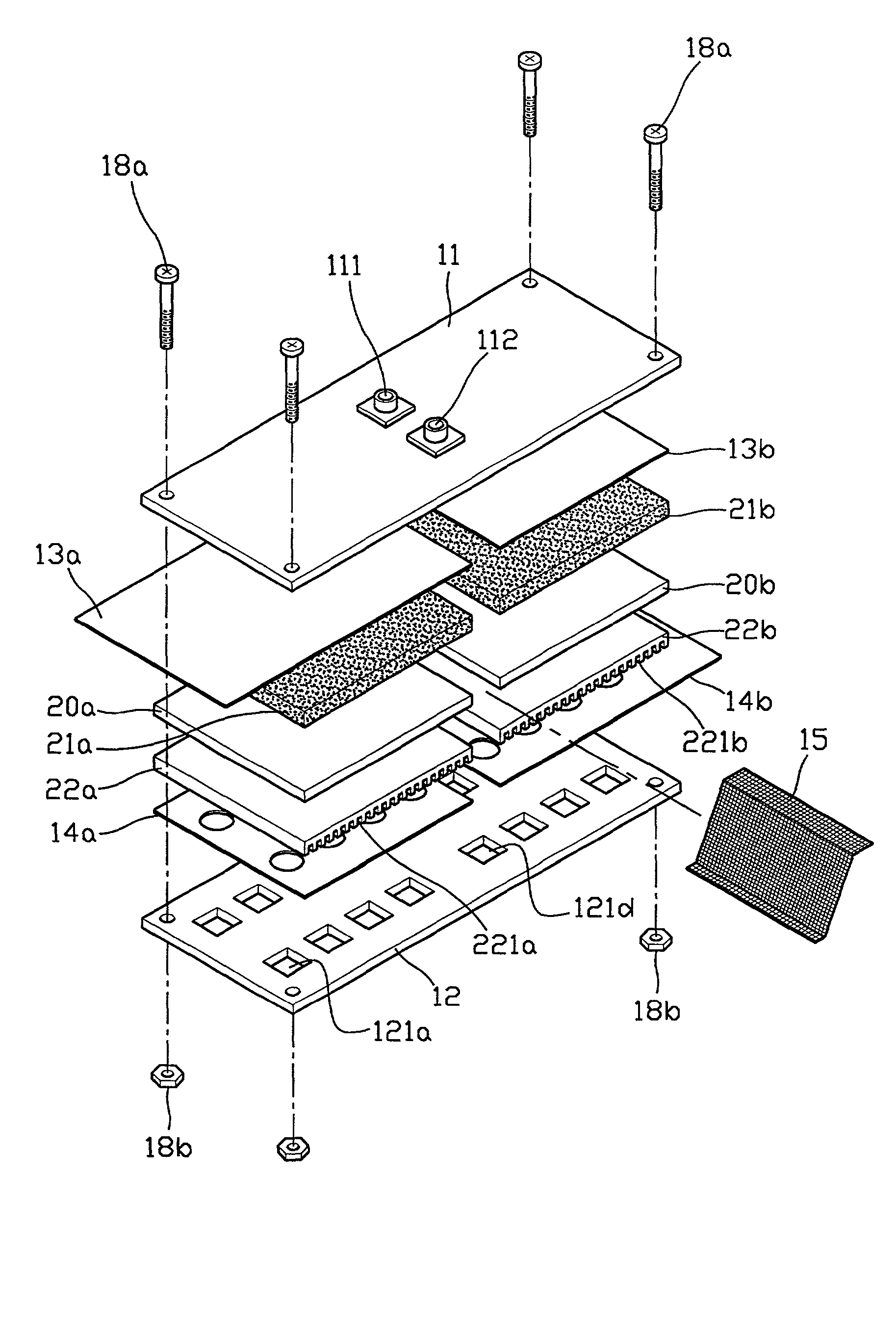
[0054] Hollows 18a and 18b are provided between the cells. Electrical connection members 15a and 15b are disposed within the respective hollows 18a and 18b. A fuel inlet 111a and a fuel outlet 112a corresponding to the hollows 18a and 18b, respectively, are disposed on the anode end plate 112a with a predetermined gap therebetween. As described in the first embodiment, each of the electrical connection members 15a and 15b is electrically connected to cells at both sides of each of the hollows 18a and 18b, so that the cells are connected in series. Here, one end of each electrical connection member 15a or 15b is connected to an anode collector plate 13a or 13b in one cell, and the other end is connected to a cathode collector plate 14b or 14c in the next cell. Fuel flow stoppers 16a and 16b are disposed in the lower portions of the respective hollows 18a and 18b to prevent fuel flowing in the upper portion of the respective hollows 18a and 18b from flowing toward cathodes.

[0055] In a...

second embodiment

[0059] Referring to FIG. 11, unit cell packs 10a and 10b each having a structure described in the second embodiment are disposed on and beneath an intermediate layer 200. In other words, the unit cell packs 10a and 10b share the intermediate layer 200 as an anode end plate and have cathode end plates 12c and 12d, respectively.

[0060] In FIG. 11, each of the unit cell packs 10a and 10b disposed on and beneath the intermediate layer 200 includes three cells which are arranged in line with hollows 18a and 18b or 18c and 18d therebetween. Electrical connection members 15a, 15b, 15c and 15d are disposed in the hollows 18a, 18b, 18c and 18d, respectively. Each of the electrical connection members 15a, 15b, 15c and 15d is connected to an anode collector plate 13a, 13b, 13e or 13f of one cell and to a cathode collector plate 14b, 14c, 14d or 14f in an adjacent cell. Fuel flow stoppers 16a, 16b, 16c and 16d are disposed at portions near cathodes in the respective hollows 18a, 18b, 18c and 18d...


PUM


Abstract

A proton exchange membrane fuel cell and a direct methanol fuel cell pack using a monopolar electrode are provided. The fuel cell pack includes a plurality of cells each having a membrane in its middle and a cathode and an anode at both sides of the membrane, collector plates contacting the cathode and the anode, respectively, in each cell, and an electrical connection member for electrically connecting adjacent cells. The cells are evenly disposed on an arbitrary plane with a hollow interposed between two adjacent cells. The electrical connection member is positioned in the hollow. The fuel cell pack also includes a porous fuel diffusion member contacting the anode of each cell; a porous air contact member contacting the cathode of each cell; an anode end plate and a cathode end plate disposed at the side of the anodes of the cells and at the side of the cathodes of the cells, respectively, for protecting the cells; a fuel supply and discharge unit for supplying fuel toward the anodes in the hollow and discharging the fuel; a fuel flow stopper disposed at a portion at the part of the cathodes in the hollow, for preventing fuel flowing at a portion at the part of the anodes in the hollow from flowing toward the portion at the part of the cathodes in the hollow; and a sealing member for sealing the anodes of the cells and the portion of the hollow corresponding to the anodes. Accordingly, circulation of fuel for the plurality of cells is performed through a single inlet and a single outlet so that a fuel supply line is very simple compared to a structure of a fuel supply line for each cell in a conventional cell pack having a structural limitation. In addition, the cell pack generates current of a high density without a separate cooling device.

Description

[0001] 1. Field of the Invention[0002] The present invention relates to a cell pack of a proton exchange membrane fuel cell and a direct methanol fuel cell.[0003] 2. Description of the Related Art[0004] A proton exchange membrane fuel cell (PEMFC), which is a future clean energy source which can substitute for fossil energy sources, has a high power density and a high energy conversion efficiency. In addition, a PEMFC can operate at a room temperature and can be miniaturized and hermetically sealed so that it can be applied to low emission automobiles, generating systems for home use, mobile communication equipment, medical instruments, military equipment, equipment for the space industry and so on. That is, a PEMFC can be applied to a variety of fields.[0005] A PEMFC is a generating system which generates direct current electricity from the electrochemical reaction between hydrogen and oxygen. For the PEMFC, a single cell includes an anode, a cathode and a proton exchange membrane ...

Claims


Application Information

Patent Timeline
IPC IPC(8): H01M4/86H01M8/00H01M8/02H01M8/10H01M8/24
CPCH01M8/1009H01M8/241Y02E60/50H01M2300/0082H01M8/249H01M8/2418Y02P70/50H01M8/10H01M8/24
Inventor CHANG, HYUKLIM, CHAN
Owner SAMSUNG SDI CO LTD
Why Eureka
Try Eureka