However, since the center of gravity of the positioning mechanism and the center of gravity of the
actuator exist at different positions, difficulty is encountered in executing track
position control with high accuracy and recording a
servo signal with a high precision.
There are problems which arises with this technique, however, in that an unstable state of a flying head due to the irregularities exerts adverse influence on recording /
reproduction, cost rises because there is a need to use a high-power
laser beam for the formation of the irregularities, and the one-by-one formation of the irregularities is time-consuming.
Thus, although the above-mentioned technique is relatively applicable to a flexible
floppy disk easy to press or a low-corecivity magnetic disk which does not require too great contact, considerable difficulty is experienced in applying it to a high-density recording magnetic disk using a
hard substrate, whose corecivity exceeds 3000 Oe.
That is, in the case of the magnetic disk using a
hard substrate, there is a possibility that microscopic
dirt particles or the like get between the master disk and the medium at the contact to produce defects on the medium or damage the high-priced master disk.
In particular, for a glass substrate, the contact therebetween does not reach satisfaction because the
dirt particles get therebetween, which makes the magnetic print impossible or causes cracks on the magnetic recording medium.
Furthermore, with the technique disclosed in U.S. Pat. No. 3,869,711, although a pattern formed obliquely with respect to a track direction of a disk is recordable, the recording is limited to the formation of only a pattern with a low
signal strength.
However, in the case of the oblique pattern, a
magnetic field for the reverse
magnetization becomes perpendicular to a gap defined by the ferromagnetic layer of the master disk, which makes it difficult to tilt the
magnetization in a desired direction.
In consequence, a part of the magnetic field escapes to the ferromagnetic layer to make it difficult to
expose a desired portion to a sufficient magnetic field at magnetic print so that a sufficient reverse
magnetization pattern is difficult to form and a high
signal strength is hard to obtain.
Moreover, since the area subjected to recording is limited to the heating area while the recording in other than the heating area cannot be made even if a magnetic field is brought to strike thereon, the recording of a clear magnetic pattern is possible without bringing a mask or the like into contact with the medium.
If the magnetic pattern is made more minute up to 1 to 2 .mu.m or formed in terms of submicron, because of the limit to the
processing accuracy, difficulty can be encountered in patterning a mask with high precision, and the alignment precision between the mask and the medium can deteriorate so that a magnetic pattern cannot be formed with sufficiently high accuracy.
However, since a high thickness adversely affects the thickness reduction of a magnetic recording apparatus, preferably, it is less than or equal to 3 mm.
If exceeding 20000 Oe, a large external magnetic field is required for batch magnetization, and the ordinary magnetic recording can be difficult.
If the
magnetic layer is heated up to an excessively high temperature, the magnetic layer can deform.
In a case in which the magnetic disk is a longitudinal magnetic recording medium, with respect to a high-density magnetic disk with a high corecivity, the conventional magnetic printing method encounters difficulty in saturation recording and difficulty in formation of a magnetic pattern with a
high magnetic field strength, and enlarges the
full width at half maximum.
However, if excessively high, the formation of a magnetic pattern becomes difficult.
Moreover, since no magnetization takes place even if a magnetic field is brought to strike on other than the heated area, the formation of a
magnetic domain can be limited to a heated area.
When an energy beam is applied in a state where a
photomask and a magnetic disk are brought closely into contact with each other, depending upon material, the mask absorbs the energy beam so that it is heated and the temperature of the contacting surface of the magnetic disk rises, thereby sometimes making it difficult to draw a magnetic pattern clearly.
Such radially continuous pattern or an oblique pattern with respect to the
radius was hard to produce through the use of a conventional
servo pattern forming method of recording a
servo signal for each track while rotating a disk.
When the minimum width of the magnetic pattern becomes less than or equal to 2 .mu.m, severer difficulty is experienced in alignment between the magnetic disk and the mask; therefore, the application of this technique produces a large.
The poor servo pattern accuracy produces rough
head position control.
However, since the
beam diameter of the energy beam becomes smaller due to being narrowed down, the pattern area formable at a time becomes small.
In particular, as the high-density recording is in progress, not only a servo signal is hard to write but also the servo recording is a main cause of an increase in cost; therefore, great effects are obtainable when the present invention is applied to a high-density recording magnetic disk.
If power exceeding this value is applied, there is a possibility that the magnetic disk surface is damaged by the pulse-like energy beam to be deformed.
If the deformation causes the roughness Ra exceeding 3 nm or the
waviness exceeding 5 nm, this can interfere with the traveling of the flying / contact head.
Below this value, the temperature of the magnetic layer is hard to increase and the magnetic printing is hard to conduct.
A magnetic layer, which receives the influence of an external magnetic field below 100.degree. C., tends to have a
magnetic domain with low stability at the
room temperature.
Below this value, the possibility exists that the magnetization becomes insufficient.
Moreover, since no magnetization is made even if a magnetic field is applied to other than the heated area, the formation of a
magnetic domain is limited to the heated area.
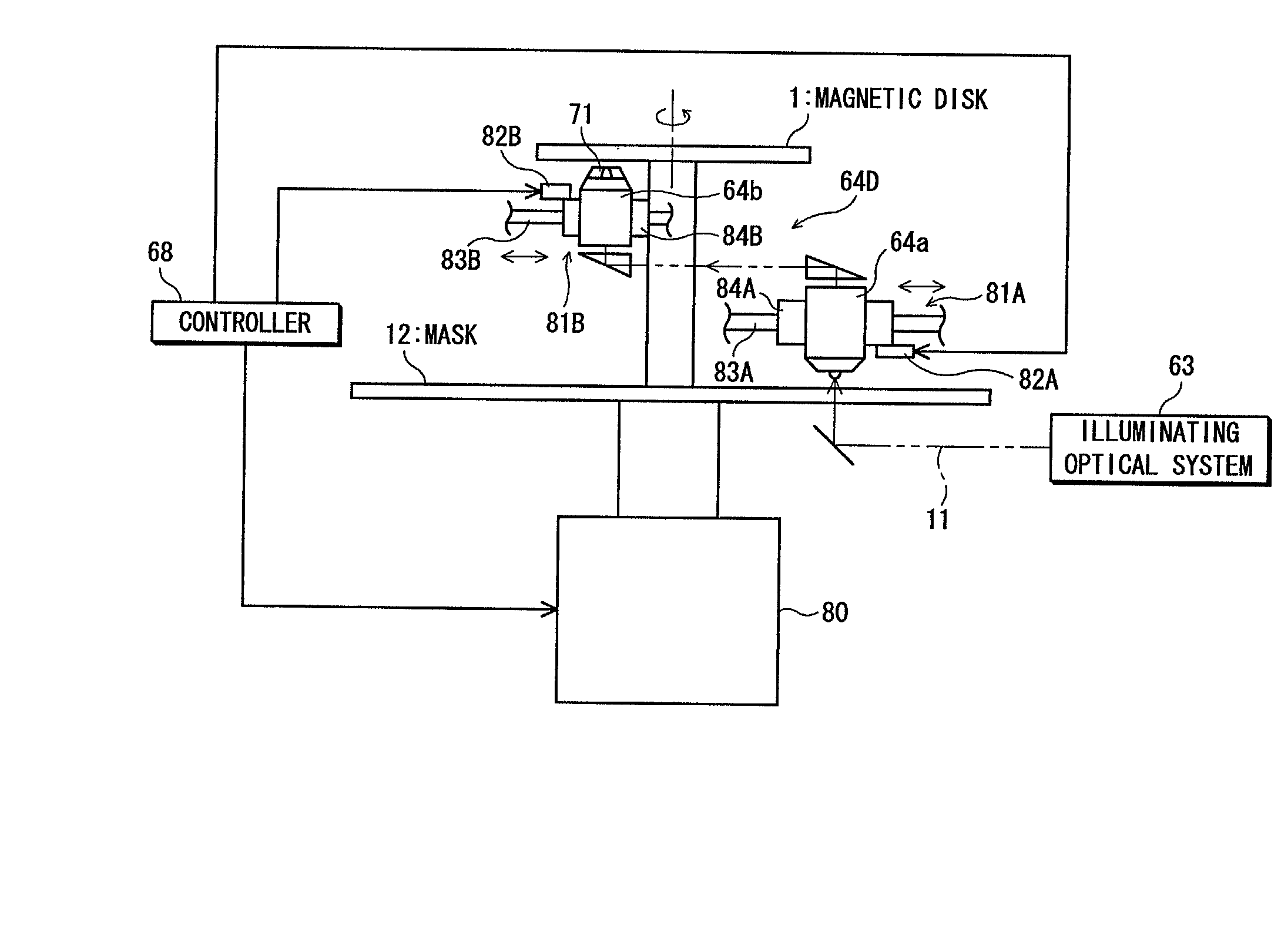
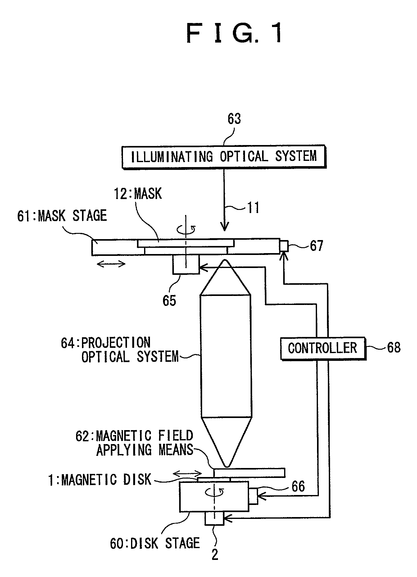
However, in this case, there is a need to use a large-sized illuminating optical
system 63 (particularly,
light source 41) or projection optical
system 64, which leads to an increase in cost.
In particular, in a case in which the magnetic disk 1 is a longitudinal magnetic recording medium, there is a need to apply a magnetic field in a disk circumferential direction for the formation of a magnetic pattern, but difficulty is encountered in applying the magnetic field to the entire surface of the magnetic disk 1 in the disk circumferential direction at a time.
However, in the case of a conventional servo pattern forming method, because of the influence of vibration occurring due to the difference in center of gravity between an external pin and an
actuator, the limit of a write track width becomes 0.2 to 0.3 .mu.m, and the servo pattern accuracy cannot catch up with the increase in
track density, which tends to cause the hindrance to the
recording density improvement and cost reduction of a magnetic recording apparatus.
With the conventional servo pattern forming method in which a servo signal is recorded by each track while a disk is rotated, it is relatively hard to form such a radially continuing pattern or oblique pattern, and it is required to use complicated calculation or arrangement therefor.
Since a hole is made in the drive in addition to the use of the dedicated servo write, these works are required to done in a clean room, which leads to a cumbersome process and an increase in cost.
In the case of a magnetic recording apparatus accommodating a magnetic disk having a servo pattern formed in this way, the aforesaid servo pattern writing process becomes unnecessary.
