
L band amplifier with distributed filtering

a filtering and l band technology, applied in electromagnetic transmission, transmission, active medium materials, etc., can solve the problems of reducing power conversion efficiency, reducing the efficiency of more length dependent reductions, and significantly compromising the noise performance of amplifiers

Inactive Publication Date: 2002-08-08
II VI DELAWARE INC
View PDF0 Cites 10 Cited by
  • Summary
  • Abstract
  • Description
  • Claims
  • Application Information

AI Technical Summary

Benefits of technology

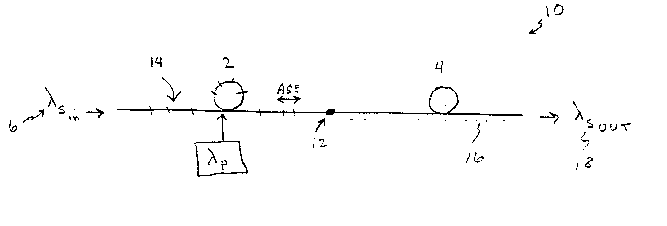
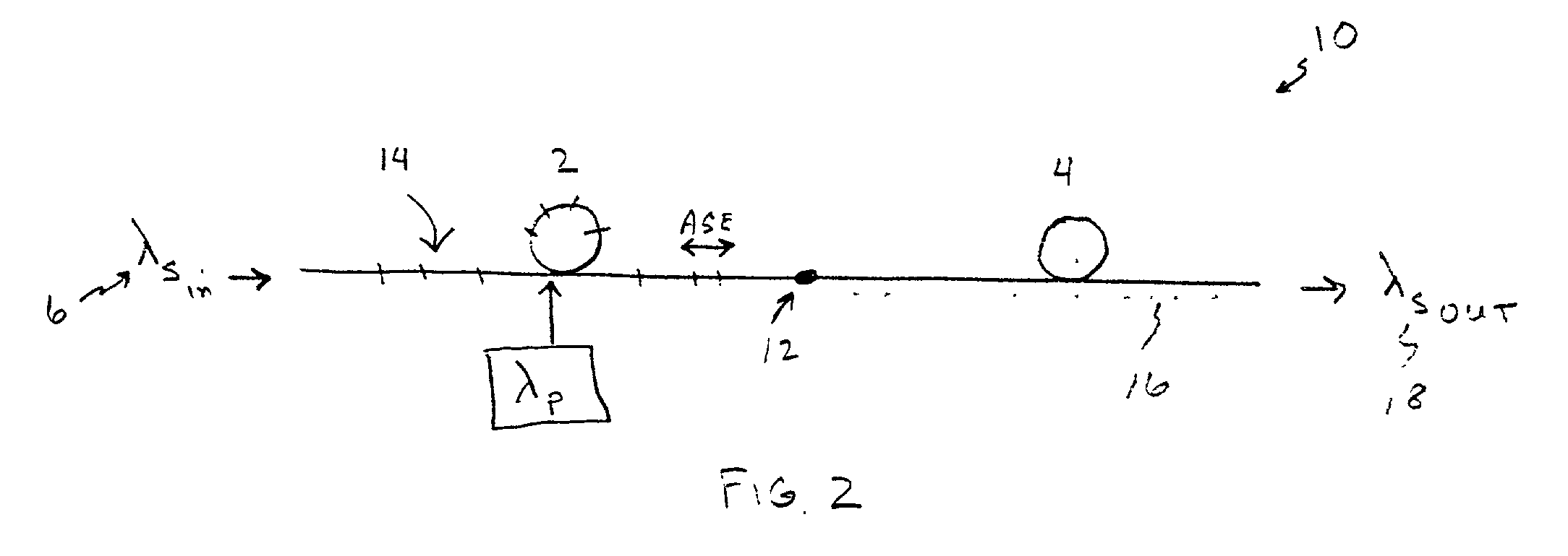
[0015] The invention described herein particularly provides a device and a method for amplifying light signals in the erbium L-band having improved performance over L-band amplifiers without distributed filtering. Distributed filtering according to the invention substantially eliminates the out-of-band ASE generated in the amplifier due particularly to hard pumping, which in turn allows the amplifier to operate at a higher average inversion without self-saturation by the C-band ASE. Higher average inversion operation allows for a shorter active coil length for obtaining target gain values and in addition contributes to improved power conversion efficiency due to a reduction in background loss. Amplifier noise figure is also improved by the ability to achieve the target L-band stage gain at a higher inversion. The invention thus also provides benefits for amplifier circuit layout and packaging considerations.
[0016] Although the device according to the invention is illustratively described as a fiber optical amplifier, it is not so limited as a planar architecture, for example, can also implement the invention.

Problems solved by technology

The intrinsic reduction in gain / loss ratio for an L-band amplifier over a C-band amplifier results in reduced power conversion efficiency.
This is further exaggerated by the reduction in average inversion which accompanies self-saturation and which reduces the already low gain coefficient even further, resulting in even more length dependent efficiency reduction.
Furthermore, if the first stage of a multistage amplifier is operated at low inversion, the noise performance of the amplifier is significantly compromised.
However, operation at high inversion produces C-band ASE which will reduce the power conversion efficiency of the amplifier.

Method used


Image

  • L band amplifier with distributed filtering
  • L band amplifier with distributed filtering
  • L band amplifier with distributed filtering

Examples


Embodiment Construction

[0032] To provide the reader with a clearer understanding of the invention, the term "distributed filter" as used herein refers to filtering that occurs over some finite physical portion of the filtered gain stage (i.e., the active fiber), as opposed to at merely a single or discrete location in the gain stage. Thus the filter may, for example, be distributed over a length of the gain stage practically ranging from about 25% of the fiber to substantially the entire gain stage depending upon how well the distributed filter provides filtering of the ASE produced by the amplifier. This will be described in greater detail below in relation to the amplifier filtering embodiments of the invention; however, it can be said that the distributed filter may include a plurality of discrete filters distributed over the physical portion of the gain medium to provide effective filtering or, alternatively, a physically continuous filter distributed over a portion of the gain medium.

[0033] A helpful...


PUM


Abstract

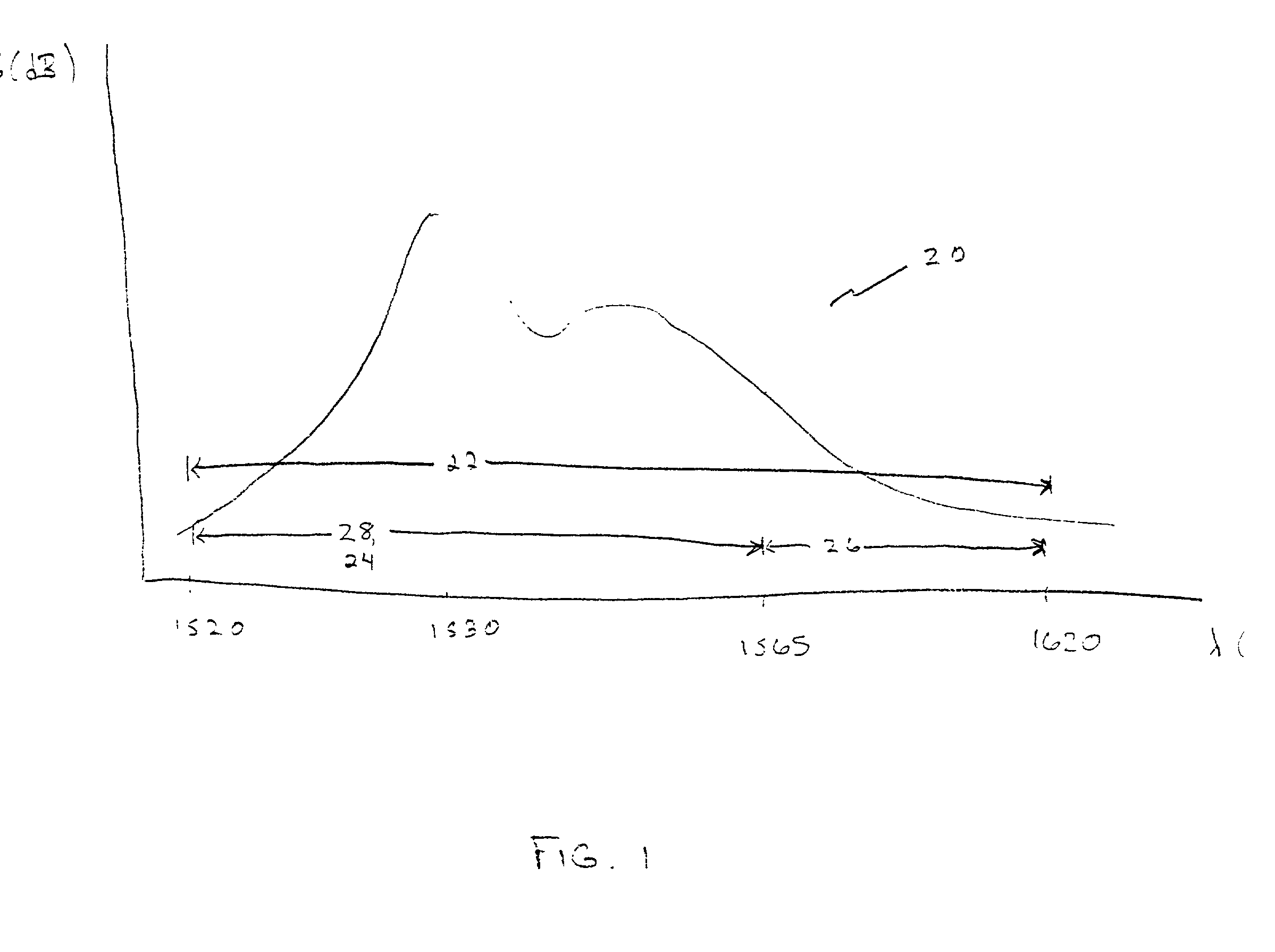
An L-band optical amplifier has a rare earth doped gain medium including a filter distributed over a finite physical portion of the gain medium. The filter is distributed over between about 25% to substantially the entire length of the gain medium. The distributed filter substantially eliminates out-of-band light emission (C-band ASE, 1520 nm-1565 nm) and thus improves the performance of L-band amplification (1565 nm-1620 nm). Examples of distributed filters include discrete type filters such as long period gratings, or continuous type filters such as rare earth doped, twin core fibers, non-adiabatically tapered fibers and coaxial resonant ring fibers.

Description

[0001] 1. Field of the Invention[0002] The present invention relates generally to the field of optical communications and in particular to a device and method for providing optical signal amplification in the longer wavelength or tail region of a given gain spectrum.[0003] 2. Technical Background[0004] Rare earth doped optical amplifiers and particularly erbium-doped fiber amplifiers (EDFAs) are used extensively and almost exclusively to amplify optical signals in today's communications systems and networks. The well-known benefits of rare earth doped optical amplifiers include cost effectiveness, good noise performance, a relatively broad polarization insensitive bandwidth, low insertion loss, and improved crosstalk performance over other amplifier technologies. EDFAs are increasingly being used in wavelength division multiplexed (WDM) optical communications systems and networks.[0005] As service providers strive to keep up with the ever-growing demand for capacity, attention has b...

Claims


Application Information

Patent Timeline
Patent Type & Authority Applications(United States)
IPC IPC(8): H01S3/067H01S3/06H01S3/10H01S3/16H04B10/17
CPCH01S3/06754H01S3/10023H01S3/1608H01S2301/02H04B10/291
Inventor MINELLY, JOHN D.YADLOWSKY, MICHAEL J.
Owner II VI DELAWARE INC
Learn More