Constant detecting apparatus for brushless DC motor, control apparatus for brushless DC motor, and program for detecting constant of brushless DC motor

a technology of brushless dc motors and constant detecting apparatuses, which is applied in the direction of electronic commutators, dynamo-electric gear control, and dynamo-electric converter control. it can solve problems such as errors, voltage vector errors, and errors, and achieve easy calculation and inducement

Inactive Publication Date: 2002-08-22
HONDA MOTOR CO LTD
View PDF0 Cites 77 Cited by
  • Summary
  • Abstract
  • Description
  • Claims
  • Application Information

AI Technical Summary

Benefits of technology

0039] According to the control apparatus of the brushless DC motor having the structure described above, while the brushless DC motor is rotating, the phase resistance value that increases along with the increase in the winding temperature can be suitably calculated, and in addition, an induced voltage that decreases along with the increase on the temperature of the permanent magnet used for the mag

Problems solved by technology

Due to the shifting of the position sensor, there are the problems that errors occur in the phases of each of the current phases and the phases of each of the voltage phases, and that errors occur in the results of the calculation of the d axis inductance and the q axis inductance.
In addition, while the brushless DC motor is being rotated, the winding resistance value fluctuates along with the fluctuations in the temperature of the windings that are wound around the rotor, the induced voltage fluctuates along with the fluctuations in the temperature of the permanent magnet of the rotor, the iron loss fluctuates, or the like, and thereby there are the problems that errors occur in the voltage vector, and that errors occur in the results of the calculation of the d axis inductance and the q axis inductance.
Here, in the case that the d axis current command value and the q axis current command value ar

Method used


Image

  • Constant detecting apparatus for brushless DC motor, control apparatus for brushless DC motor, and program for detecting constant of brushless DC motor
  • Constant detecting apparatus for brushless DC motor, control apparatus for brushless DC motor, and program for detecting constant of brushless DC motor
  • Constant detecting apparatus for brushless DC motor, control apparatus for brushless DC motor, and program for detecting constant of brushless DC motor

Examples


Embodiment Construction

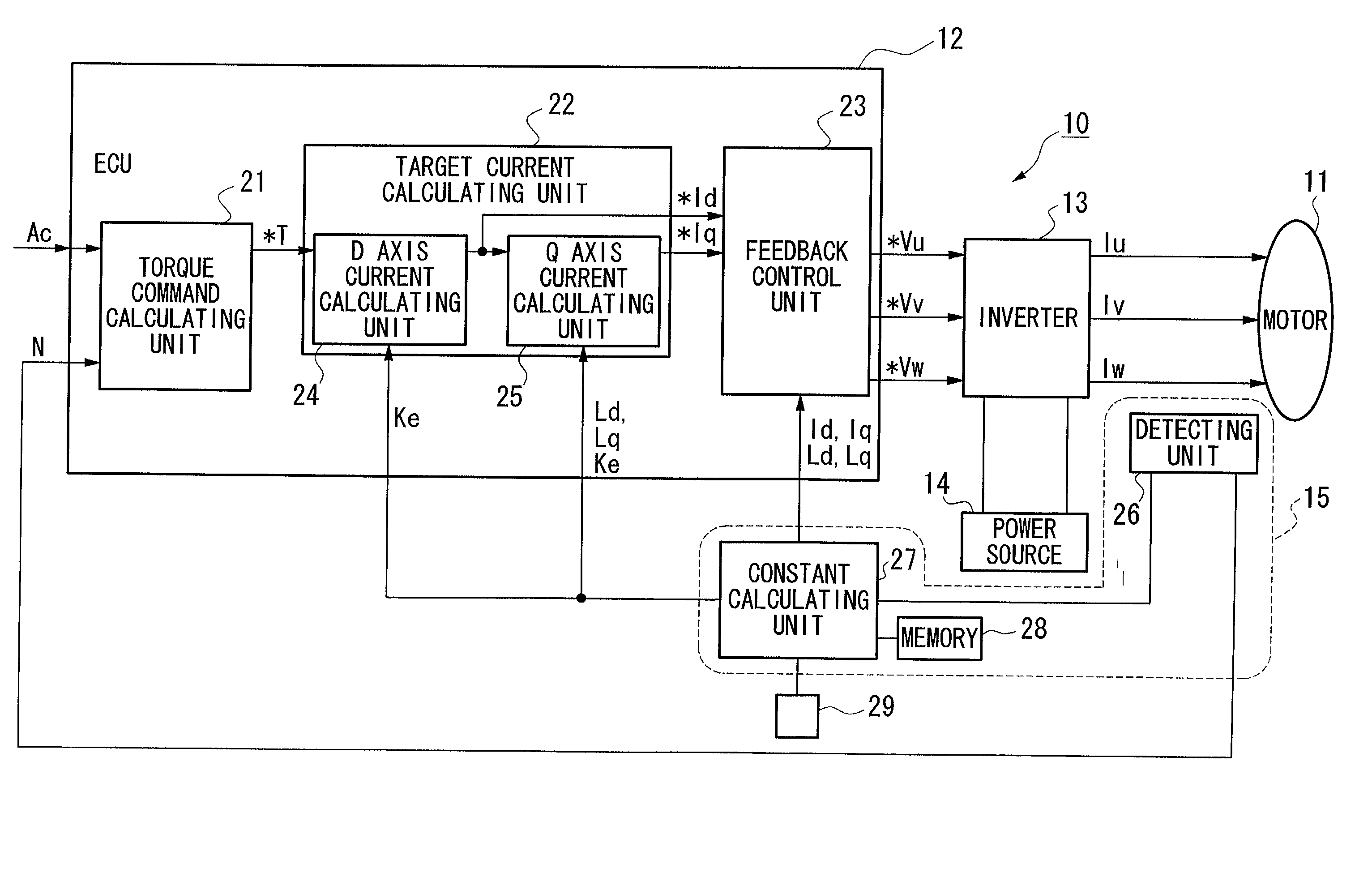
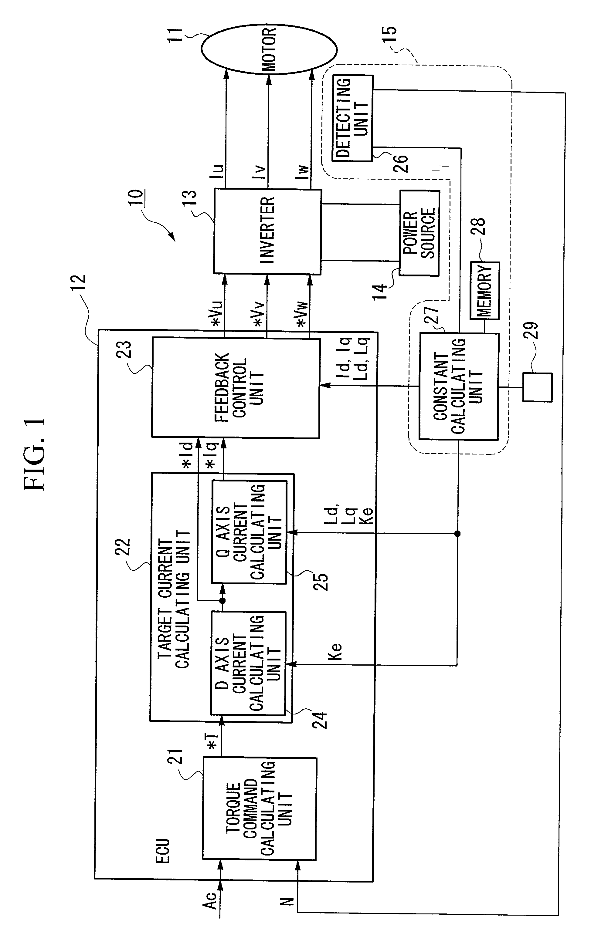
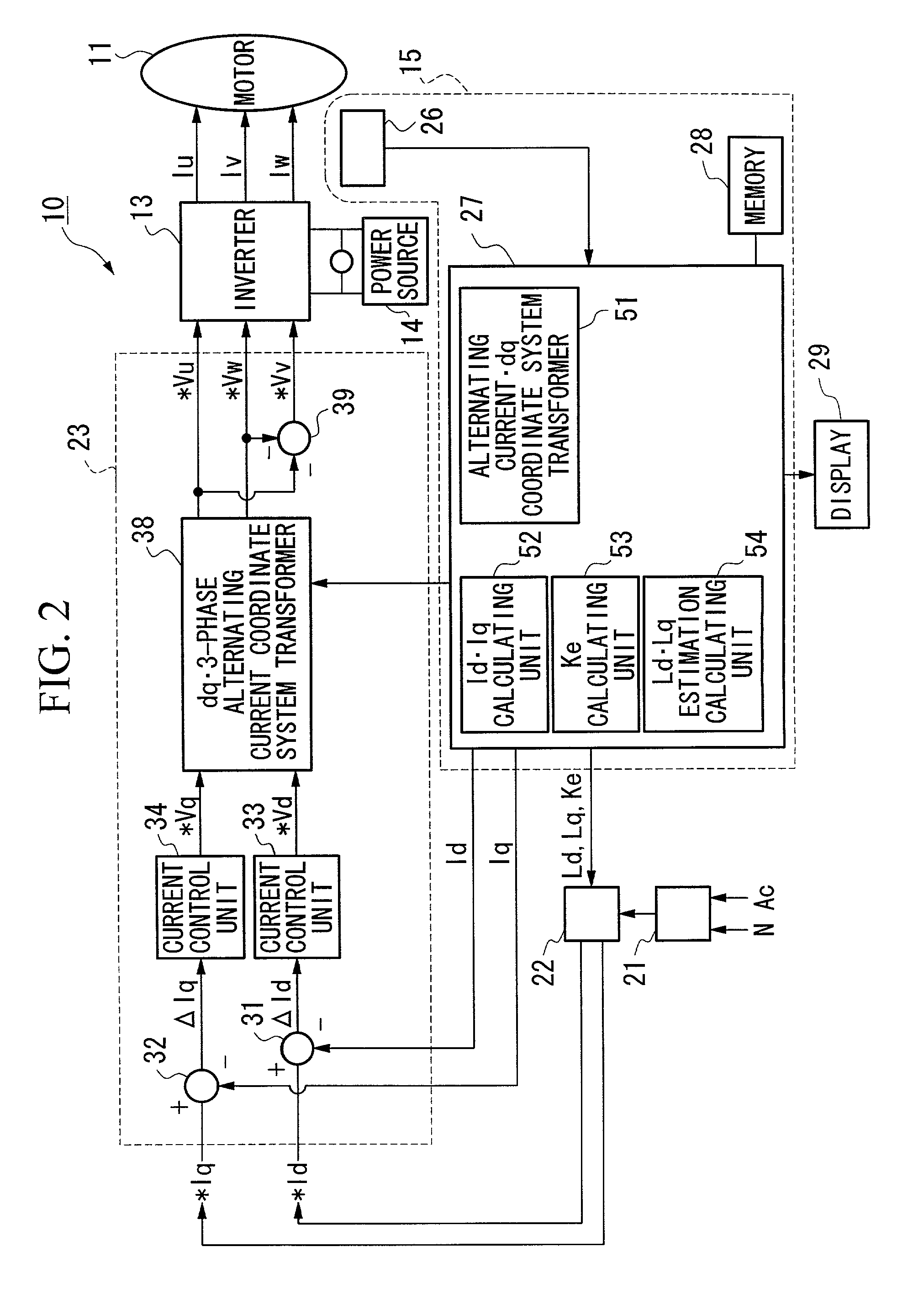
[0068] Below, an embodiment of a control apparatus for a brushless DC motor of the present invention will be explained while referring to the drawings. FIG. 1 is a structural drawing of the control apparatus 10 for the brushless DC motor according to an embodiment of the present invention, FIG. 2 is a structural drawing showing the concrete structure of the feedback control unit 23 and the constant calculating unit 27 shown in FIG. 1, and FIG. 3 is a structural drawing showing the concrete structure of the detecting unit 26 of the constant detecting apparatus 15 for the brushless DC motor shown in FIG. 1.

[0069] The control apparatus 10 for the brushless DC motor 10 (below, referred to as the "motor control apparatus 10") according to the present embodiment drives and controls the brushless DC motor 11 (below, referred to as the "motor 11") mounted, for example, an electric vehicle or a hybrid vehicle, and this motor 11 is structured comprising a rotor (not illustrated) having a perm...


PUM


Abstract

A constant detecting apparatus 15 comprising a detecting unit 26 and a calculating unit 27. The detecting unit 26 is structured comprising a rotation sensor 41, a torque sensor 42, a position sensor 43, a rotor temperature sensor 44, a winding temperature sensor 45, a phase voltage detector 46, and phase current detectors 47 and 47. The calculating unit 27 calculates the induced voltage constant Ke that changes depending on the motor temperature Tmag while the motor 11 is being driven based on each of the detected signals from the detecting unit 26, and at the same time, the d axis current Id and the q axis current Iq are calculated after elimination of the iron loss, and the d axis inductance Ld and the q axis inductance Lq in the actual operating state of the motor 11 are calculated.

Description

BACKGROUND OF THE INVENTION[0001] 1. Field of the Invention[0002] The present invention relates to a constant detecting apparatus for a brushless DC motor for detecting the inductance of a brushless DC motor comprising a rotor that has a permanent magnet and a stator that generates a rotating magnetic field that causes the rotation of the rotor, a control apparatus for a brushless DC motor, and a program for detecting the constant of a brushless DC motor.[0003] 2. Description of the Related Art[0004] Conventionally, vehicles such as electric vehicles and hybrid vehicles are known that have installed a brushless DC motor using a permanent magnet to provide a magnetic field as a power source for vehicle travel.[0005] A control apparatus for this kind of brushless DC motor is known that carries out feedback control such that, for example, a phase current supplied to each phase of a brushless DC motor is measured, and the measured value of the phase current is converted to an orthogonal...

Claims


Application Information

Patent Timeline
IPC IPC(8): H02P27/04B60L11/18B60L15/02H02P6/06H02P6/08H02P6/16H02P21/00H02P21/06H02P21/14H02P21/16H02P21/18H02P21/22H02P21/24H02P21/26H02P21/28H02P23/14H02P23/16H02P23/18H02P27/08
CPCB60L11/1803B60L11/1807B60L15/025B60L2220/16H02P21/06H02P21/145H02P29/0066Y02T10/643Y02T10/7005B60L50/50B60L50/51H02P21/16H02P29/662Y02T10/64Y02T10/70
Inventor ATARASHI, HIROFUMI
Owner HONDA MOTOR CO LTD
Why Eureka
Try Eureka