Supercharge Your Innovation With Domain-Expert AI Agents!

Implant with bioactive particles stuck and method of manufacturing the same

Inactive Publication Date: 2002-09-12
BRAINBASE
View PDF0 Cites 3 Cited by
  • Summary
  • Abstract
  • Description
  • Claims
  • Application Information

AI Technical Summary

Benefits of technology

[0009] In view of these points, the inventors of the present application performed various types of study and experiment as for the implant surface which had suitable roughness to bone and which could realize osteo-integration. As a result, the inventors found out a method of forming an implant having a stable surface, in which the implant had the good property of the implant having the titanium surface and the good property of the implant having the HAP coated surface. The implant can be simply manufactured from bioactive particles having osteo-conduction with low cost without bioinert impurity such as alumina particles.
[0010] Therefore, an object of the present invention is to provide an implant which has the good property of an implant having a titanium surface and the good property of an implant having a hydroxylapatite coated surface, and a method of manufacturing the same.

Problems solved by technology

However, there are the following problems in the above-mentioned conventional implants.
In the implant having the surface where the beads of titanium are sprayed in the plasma, because the plasma spraying method is the very advanced technique which requires high cost, the final implant cost becomes very expensive.
However, there is a problem in that it is difficult to remove the adherent alumina grinding particles so that bioinert alumina particles are remained on the surface of the implant.
The reason is that advanced technique is needed in the hydroxylapatite coating and it is costly.

Method used


Image

  • Implant with bioactive particles stuck and method of manufacturing the same
  • Implant with bioactive particles stuck and method of manufacturing the same
  • Implant with bioactive particles stuck and method of manufacturing the same

Examples


first embodiment

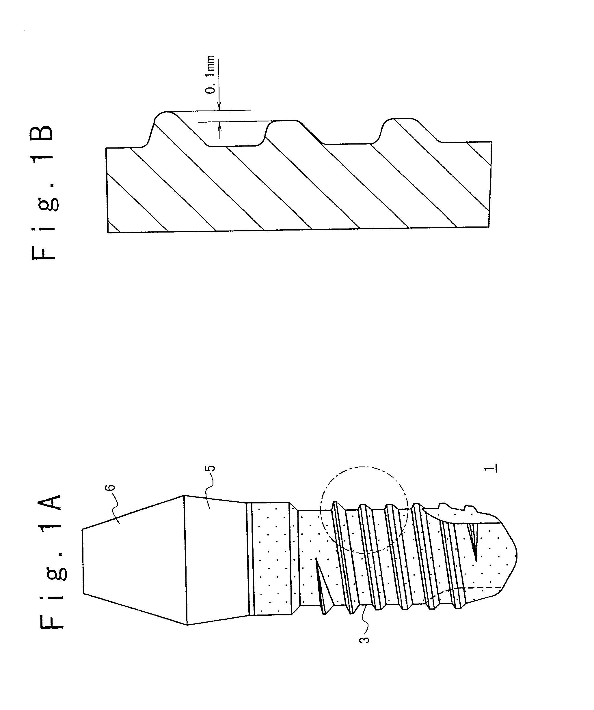
[0053] FIG. 1A shows the structure of a dentistry implant according to the present invention. Referring to FIG. 1A, a dentistry implant 1 is formed of material having bio-compatibility such as titanium or titanium alloy. The dentistry implant 1 is composed of an embedded section 3 embedded in jawbone 2, a gingiva penetrating section 5 to be located in gingiva, and a crowned section 6 which is located on the gingiva penetrating section 5. A thread is formed on the surface of the embedded section 3. As shown in FIG. 1B, the thread of an upper portion corresponding to a cortical bone section has a triangular cross section and the thread of a lower portion corresponding to a bone marrow section has a trapezoidal cross section. Therefore, the thread of the upper portion is higher than the thread of the lower portion by a predetermined height, e.g., 0.1 mm. This height difference makes insertion of the implant easy. In this example, the heights of the thread portions are different in a st...

fourth embodiment

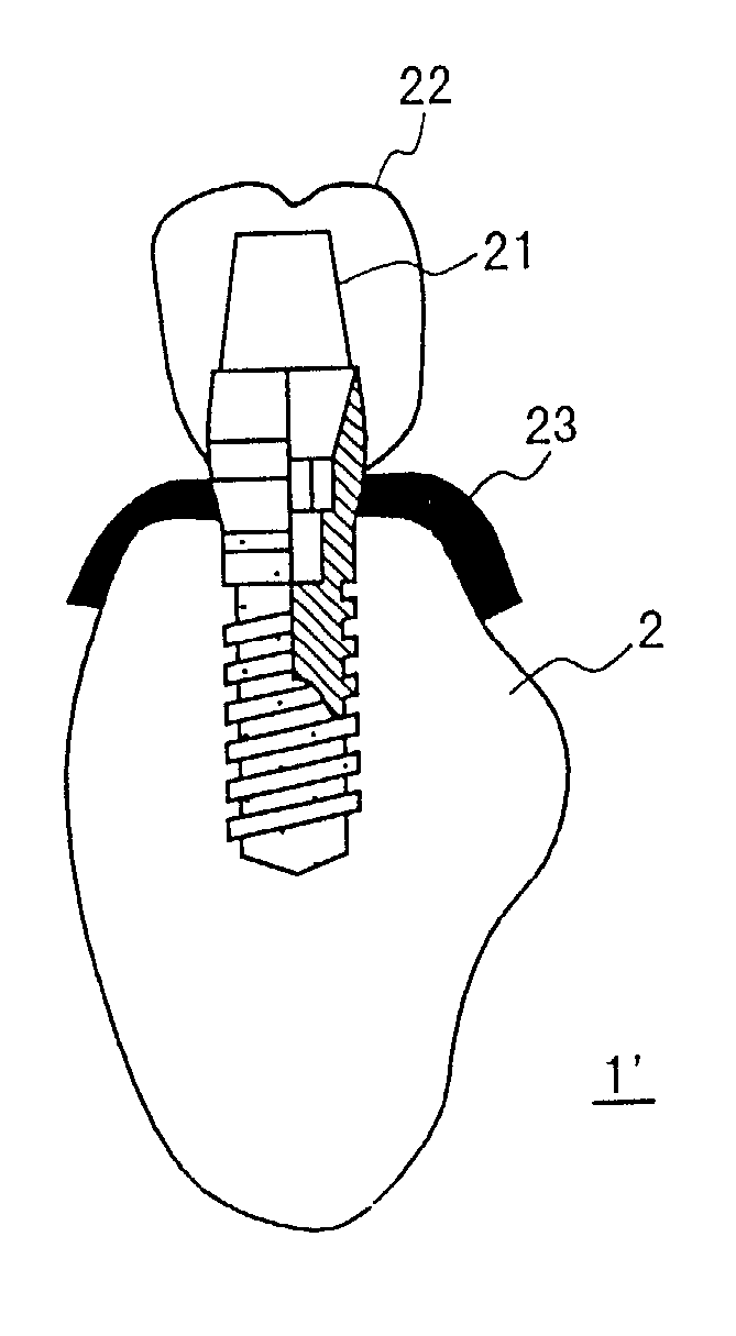
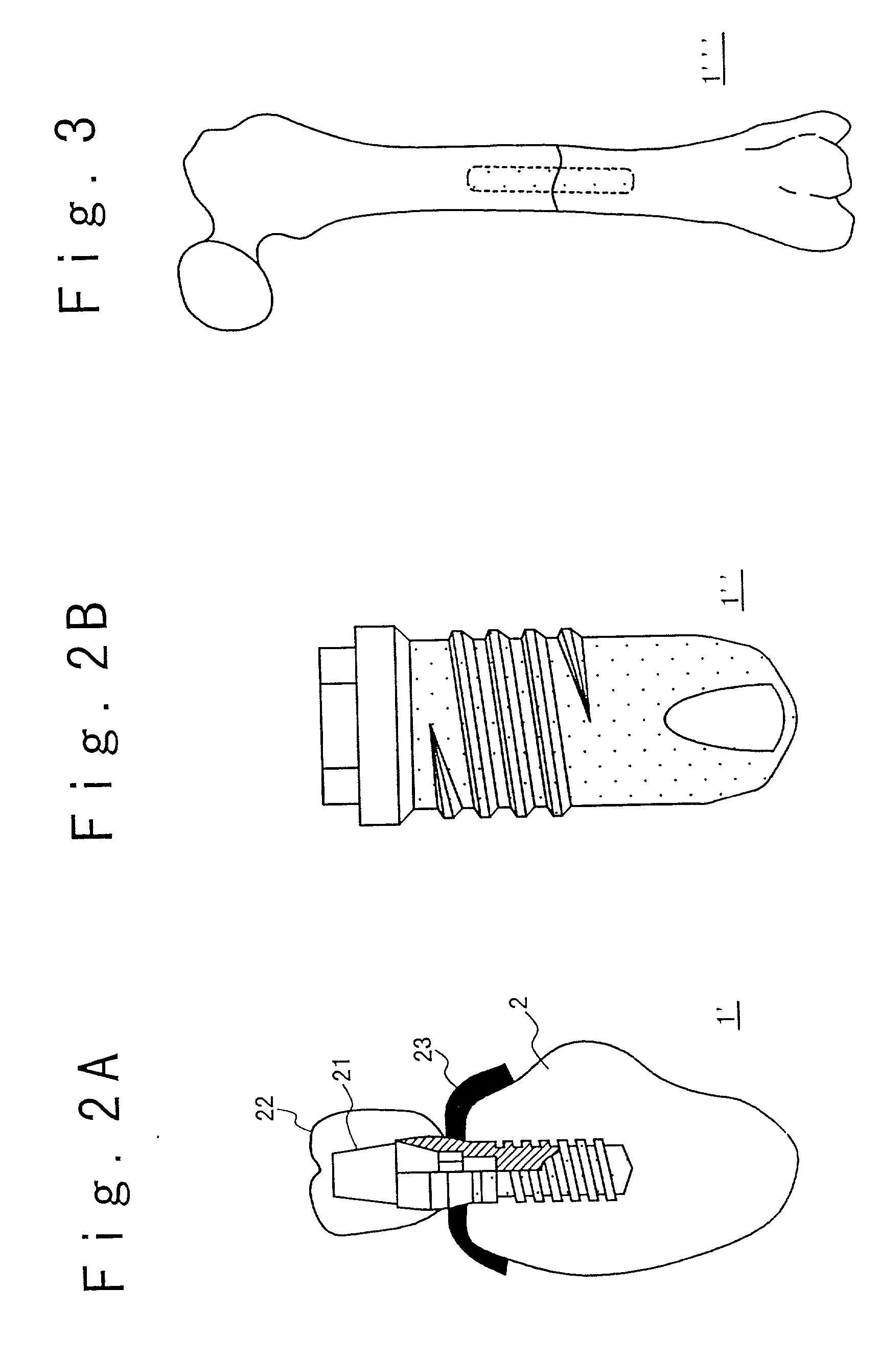
[0056] FIG. 3 shows a use example of an implant 1'" according to the present invention. In this embodiment, the implant 1'" is embedded in femur sections to couple femur sections.

[0057] In the implants shown in FIGS. 1A, 2A and 2B, the whole surface of the embedded section 3 of the implant main body member as an original implant is made rough and bioactive particles having osteo-conduction are stuck on the whole surface of the embedded section 3. However, the rough surface portion with stuck particles may be formed only below the upper portion of the thread portion.

[0058] Referring to FIG. 11, a method of manufacturing of the implant 1 in the first embodiment will be described below.

[0059] In a step S2, the gingiva penetrating section 5 and the crowned section 6 of the main body member of titanium as an original implant 1 are masked not to be hit with grinding particles. Then, while the original implant is rotated, a primary sand blasting process is performed to the surface of the e...

example 1

[0079] Only the secondary sand blasting process is performed to the embedded section 3 of the blade-shaped original implant 1 of titanium with the blasting pressure of 0.7 Pa using 45S5 glass particles with an average grain diameter of 0.1 mm. By this, as shown in FIG. 12, the blade-shaped implant formed of titanium is obtained to have an initial osteo-conduction, to have suitable surface roughness for bone, and contain a little amount of 45S5 glass 7. In this case, the gingiva penetrating section 5 and the crowned section 6 are masked such that the blasting particles do not hit. However, the secondary sand blasting process may be performed to the gingiva penetrating section 5 and the crowned section 6. In this example, the original implant is not rotated. However, it may be rotated during the sand blasting process as described above.


PUM

PropertyMeasurementUnit
Surface roughnessaaaaaaaaaa
Compatibilityaaaaaaaaaa

Abstract

An implant includes a main body member having bio-compatibility, and particles formed ofbioactive material and dispersedly provided at the surface of an embedded section of the main body member. Each of the particles has a part embedded in the embedded portion and the other part protruding from the embedded portion. The main body member is formed of titanium or titanium alloy. The particles having osteo-conduction are formed of a material selected from among a group consisting of sintered substances of hydroxylapatite, .alpha.-tricalcium phosphate, .beta.-tricalcium phosphate, tetra-calcium phosphate, a single substance of amorphous calcium phosphate, monetite, brushite, 45S4 glass, and a mixture of them. It is desirable that the embedded section surface has a surface roughness in a range of 5 to 50 .mu.m.

Description

BACKGROUND OF THE INVENTION[0001] 1. Field of the Invention[0002] The present invention relates to an implant such as an implant embedded in bones and a dentistry implant and a method of manufacturing the same, and more particularly to an implant with bioactive particles stuck and a method of manufacturing the same.[0003] 2. Description of the Related Art[0004] Titanium or titanium alloy is generally used as material of implants such as an implant embedded in bone and a dentistry implant at present. This is because when the implant is installed, the material of the implants has a state called "osteo-integration" in which the implant directly contacts bone. The osteo-integration implies the state in which there is no connective tissue between the bone and the implant. If other material is used, there is a case that the osteo-integration is not realized and a fibrous connective tissue is intervened between the implant and the bone. For this reason, the whole implant is finally covered...

Claims


Application Information

Patent Timeline
IPC IPC(8): A61C8/00A61F2/00A61F2/28A61F2/30A61L27/06A61L27/32B24C1/00B24C11/00
CPCA61C8/0006A61C8/0012A61C8/0013A61C8/0019A61C2008/0046A61F2/30767A61F2/3094A61F2002/2825A61F2002/3085A61F2002/30861A61F2002/30906A61F2310/00023A61F2310/00616A61F2310/00796A61L27/06A61L27/32B24C1/00B24C11/00Y10S623/923
Inventor HAYASHI, OSAMUSASOH, TAKAMASAOZAWA, FUMISADAFURUTA, ISAQFURUSAWA, TOSHITAKEICHIDA, EIJI
Owner BRAINBASE
Features
  • R&D
  • Intellectual Property
  • Life Sciences
  • Materials
  • Tech Scout
  • Unparalleled Data Quality
  • Higher Quality Content
  • 60% Fewer Hallucinations
Learn More