
Magneto-rheological damper with ferromagnetic housing insert

a technology of ferromagnetic housing and damper, which is applied in the direction of shock absorbers, mechanical equipment, transportation and packaging, etc., can solve the problems of increasing manufacturing costs and damper weight, reducing the available shear surface area and hence, the damping capacity, and increasing the performance.

Inactive Publication Date: 2002-09-19
DELPHI TECH INC +1
View PDF0 Cites 69 Cited by
  • Summary
  • Abstract
  • Description
  • Claims
  • Application Information

AI Technical Summary

Benefits of technology

[0012] The present invention provides an MR fluid damper with increased performance. The MR fluid damper of the present invention provides a desired magnetic flux return path without increasing the wall thickness of the damper body tube or changing the location of the flow gap. Thus, the desired magnetic flux return path is provided without adversely influencing the function of any other component of the MR fluid damper or diminishing its damping capacity.
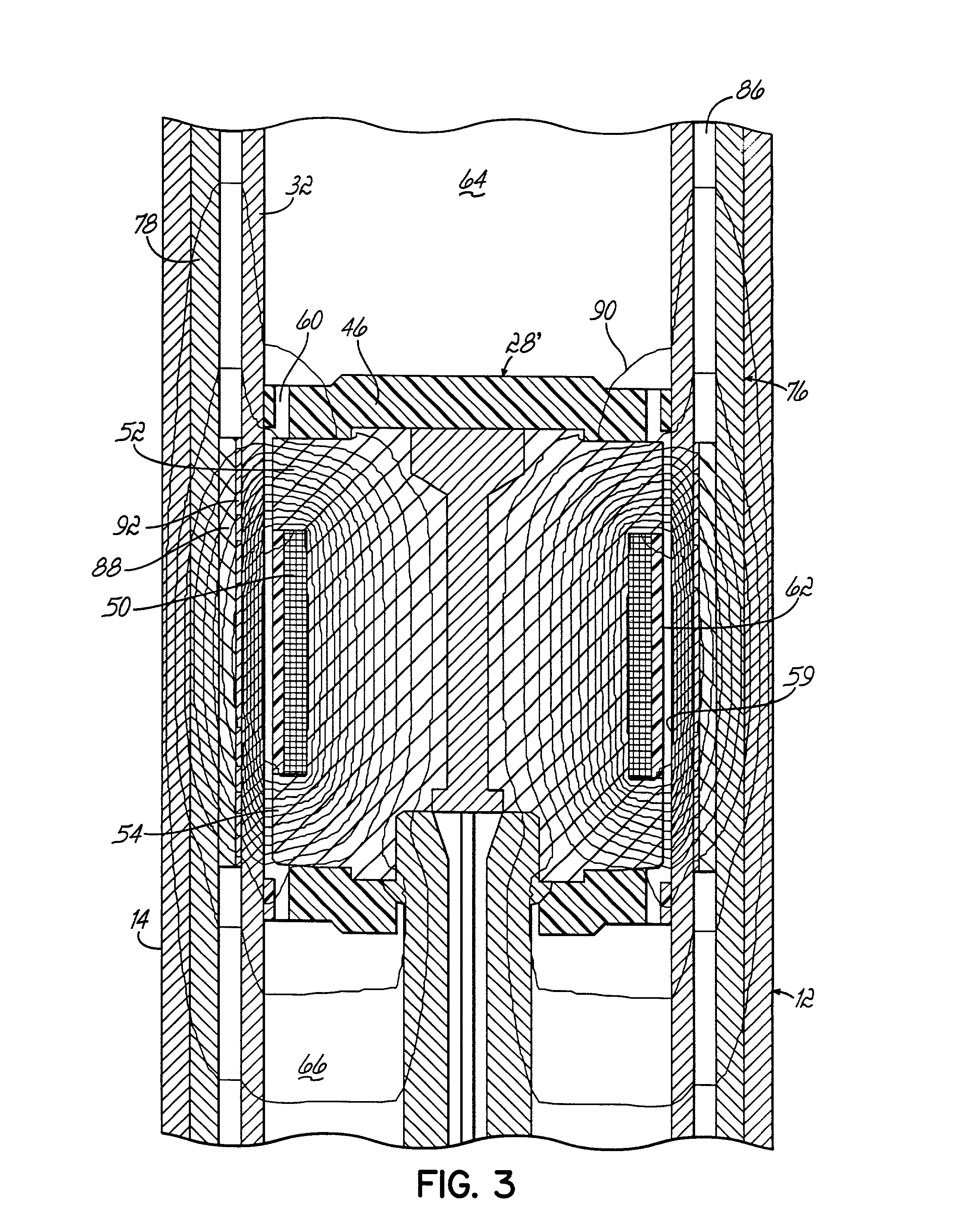
[0013] According to the principles of the present invention and in accordance with the described embodiment, the present invention provides a magneto-rheological ("MR") damper having a damper body tube containing an MR fluid. A piston assembly is disposed in the damper body tube and forms an annular flow gap between the piston assembly and the damper body tube. The piston assembly has a piston core containing ferrous material and an electromagnetic coil mounted on the piston core for generating a magnetic field. The damper further includes a ferromagnetic member positioned outside of the damper body tube substantially adjacent the piston assembly for providing at least a part of a magnetic flux return path for the magnetic field. The use of a separate member to provide an additional (or parallel) magnetic flux return path permits increased damping performance without substantially increasing the cost or weight of the MR fluid damper.

Problems solved by technology

Conventional MR fluid dampers utilizing soft magnetic material in the magnetic flux return path have various problems.
Further, the increased amount of steel in the thicker damper body tube increases manufacturing costs and damper weight.
Unfortunately, for a given diameter MR fluid damper relying upon a flux ring, the flow gap is moved inward toward the center of the damper body tube, thereby reducing the available shear surface area and hence, the damping capability.
In addition, the cross-sectional area available for the piston core is reduced, decreasing the total amount of magnetic flux that can be conducted around the magnetic circuit, yet further reducing damping capability.
Consequently, thin flux ring MR fluid dampers also have problems as do dampers utilizing either a thick flux ring or no flux ring.

Method used


Image

  • Magneto-rheological damper with ferromagnetic housing insert
  • Magneto-rheological damper with ferromagnetic housing insert
  • Magneto-rheological damper with ferromagnetic housing insert

Examples


Embodiment Construction

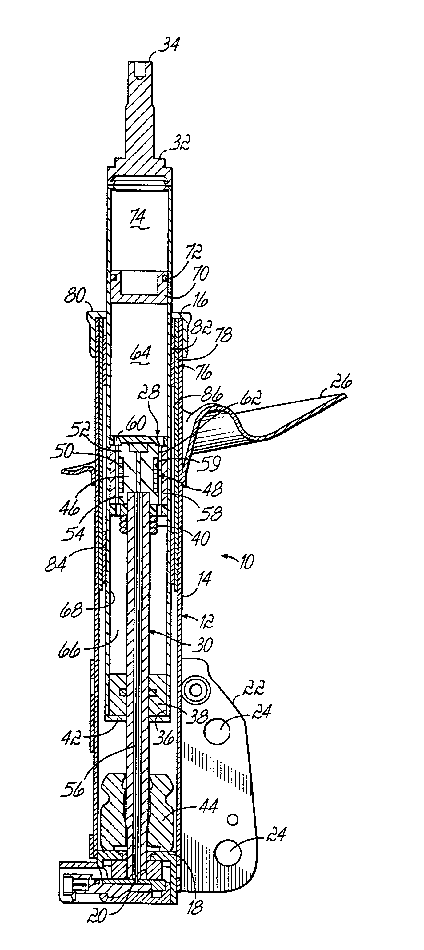
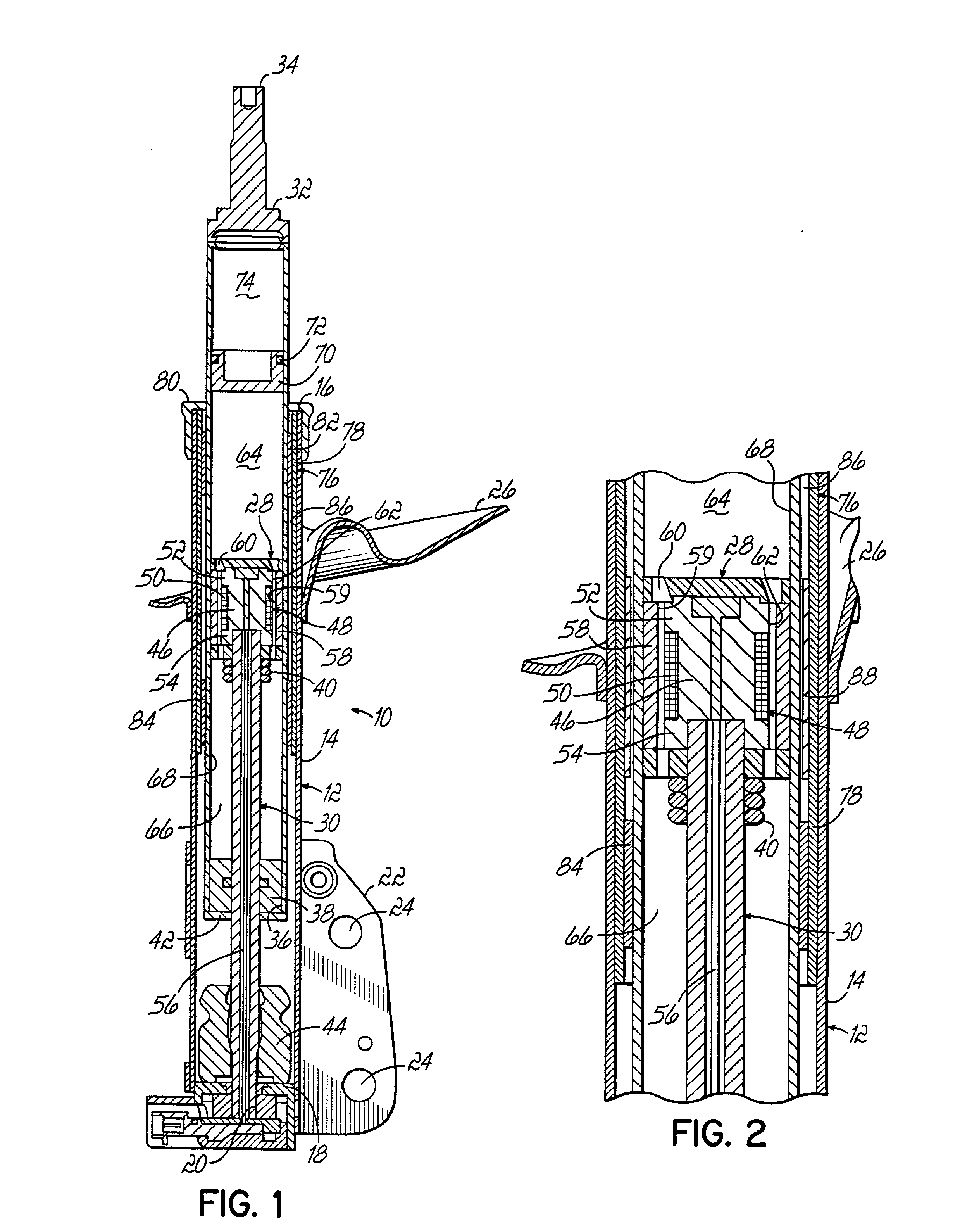
[0019] FIG. 1 illustrates a linearly-acting magneto-rheological (MR) fluid damper and in particular, a monotube gas-charged suspension strut 10. In general, the strut 10 is designed for operation as a load-bearing and shock-absorbing device within a vehicle suspension system, and is connected between the sprung (body) and unsprung (wheel assembly) masses (not shown). The strut 10 comprises a housing 12 that includes a housing tube 14 with an open end 16 and a closed end 18. The closed end 18 includes an opening 20. A mounting bracket 22 near the closed end 18 is secured in position by a suitable means such as welding. The mounting bracket 22 has suitable openings 24 for connection to the unsprung mass of the vehicle at a location such as the steering knuckle (not illustrated). A spring seat 26 is also received on the housing tube 14 and is positioned as required by the particular application within which the strut 10 will operate. The spring seat 26 is fixed in position on the housi...


PUM


Abstract

A magneto-rheological ("MR") damper having a damper body tube containing an MR fluid. A piston assembly is disposed in the damper body tube and forms an annular flow gap between the piston assembly and the damper body tube. The piston assembly has a piston core containing ferrous material and an electromagnetic coil mounted on the piston core for generating a magnetic field. The damper further includes a ferromagnetic member positioned outside of the damper body tube substantially adjacent the piston assembly for providing at least a part of a magnetic flux return path for the magnetic field.

Description

CROSS REFERENCE TO PENDING APPLICATIONS[0001] This application is also related to the following co-pending and commonly owned application which was filed on even date herewith by Ilya Lisenker: U.S. Ser. No. ______ entitled "MAGNETO-RHEOLOGICAL DAMPER WITH DUAL FLUX RING SPACER" and which is hereby incorporated by reference herein in its entirety.FIELD OF THE INVENTION[0002] The present invention relates to a magneto-rheological (MR) fluid damper, and more particularly, to a linearly-acting MR fluid damper suitable for vibration damping in a vehicle suspension system.BACKGROUND OF THE INVENTION[0003] MR fluids are materials that respond to an applied magnetic field with a change in Theological behavior (i.e., change in formation and material flow characteristics). The flow characteristics of these non-Newtonian MR fluids change several orders of magnitude within milliseconds when subjected to a suitable magnetic field. In particular, magnetic particles noncolloidally suspended in fl...

Claims


Application Information

Patent Timeline
IPC IPC(8): B60G13/00B60G15/07F16F9/53
CPCB60G13/008B60G15/07F16F9/535
Inventor LISENKER, ILYAHOPKINS, PATRICK NEIL
Owner DELPHI TECH INC
Learn More