Method for annealing domain wall displacement type magneto-optical disc and magneto-optical disc

a technology of optical discs and domain walls, applied in the field of domain wall displacement readout type magnetooptical discs, can solve the problems of limiting the improvement of laser wave length and numerical aperture of the objective lens

Inactive Publication Date: 2002-09-19
CANON KK
View PDF0 Cites 3 Cited by
  • Summary
  • Abstract
  • Description
  • Claims
  • Application Information

AI Technical Summary

Problems solved by technology

However, there is a limit to improvement of the laser ...

Method used


Image

  • Method for annealing domain wall displacement type magneto-optical disc and magneto-optical disc
  • Method for annealing domain wall displacement type magneto-optical disc and magneto-optical disc
  • Method for annealing domain wall displacement type magneto-optical disc and magneto-optical disc

Examples


example 2 example 3 example 1

Condition Annealing available available not available available of Magnetization Annealing Applied Magnet- Reversal of not available not available not available available ization Polarity Applying Intensity of +300 -300 0 .+-.300 Annealing Magnetization Length of one cycle one cycle -- one cycle Continuous Magnetization Area Reproduc- Jitter good good bad good tion Property Property Estimation Pulse Width bad Bad a little good Property bad Estimation Overall bad bad bad very good Estimation

[0064] Regarding jitter property, example 1 shows that a jitter value is low. (FIG. 6, Table 1)

[0065] The pulse widths regarding the three types of the method for applying the annealing magnetic field were estimated. Comparative examples 1 and 2 have large aberrations in the reproduction signal pulse width (FIG. 7, Table 1). Embodiment 1 has the most excellent performance among the four experiments even in pulse width.

[0066] From the result of these experiments, it is evident that, in the case whe...

embodiment 2

[0069] (Embodiment 2)

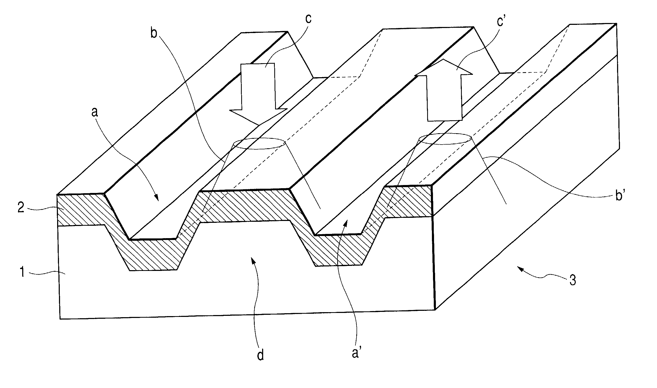
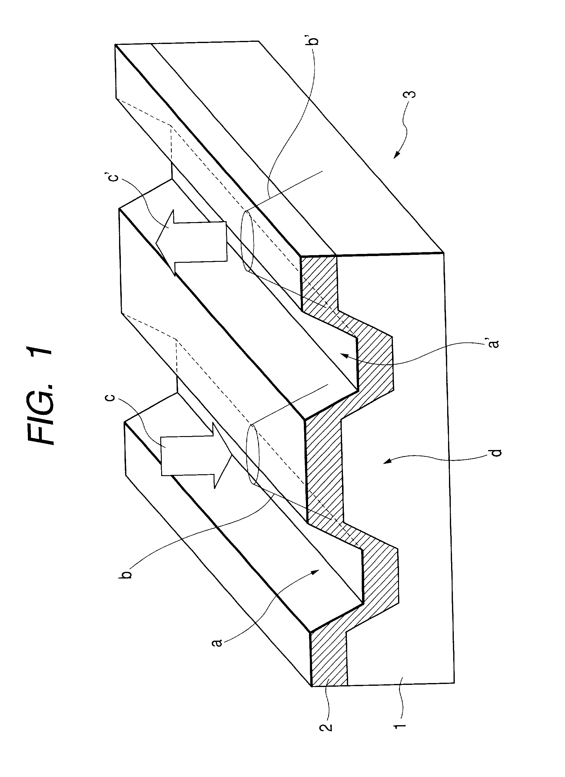
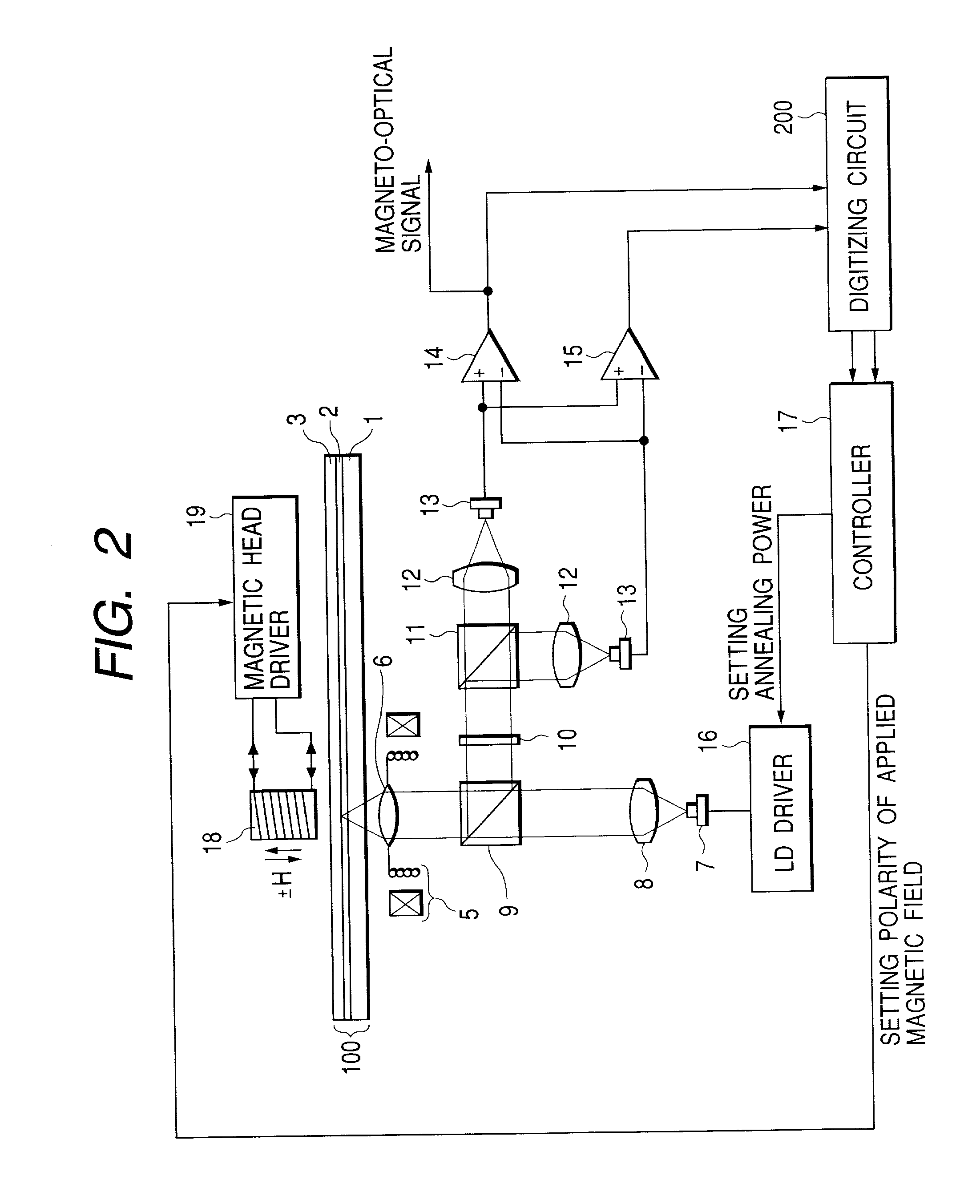
[0070] In FIG. 8 is shown a schematic diagram to show a property of the second embodiment of the annealing method of a magneto-optical disc of the present invention. In the drawing, what is different from embodiment 1 is that a ring head is used, where the magnetic disc 18, which applies the magnetic field at the time of annealing, can apply the annealing magnetic field in the in-plane direction of the face of the disc to a heated area on the recording medium. In this way, the magnetic field which is parallel to the magneto-optical disc surface can be applied to a heated annealing portion. In the case where the magnetic field is applied to the inside of the magneto-optical disc surface, there exist two directions parallel and perpendicular to the scanning direction of the light beam. In FIG. 9, an example of the annealing applied magnetic field was shown, where the annealing applied magnetic field is in the in-plane direction to the face of the magneto-optical d...


PUM

PropertyMeasurementUnit
Auxiliary magnetic fieldaaaaaaaaaa
Temperatureaaaaaaaaaa
Polarityaaaaaaaaaa

Abstract

A manufacturing method of a domain wall displacement type magneto-optical recording medium comprises the steps of depositing a magnetic layer on a substrate to prepare a disc, and irradiating the magnetic layer with a converged light beam while applying a magnetic field and annealing the magnetic layer a converged light beam between information tracks. A domain wall displacement type magneto-optical disc comprises a domain wall displacement layer in which a domain wall displaces, a memory layer that holds a recording magnetic domain according to information, a switching layer that is provided between the domain wall displacement layer and the memory layer and has a Curie temperature lower than that of those layers, and a disconnecting area that is provided in the domain wall displacement layer and disconnects a switching connection between information tracks, wherein the polarity of a residual magnetization at a boundary between the information track and the disconnection area is oriented in a certain direction.

Description

[0001] 1. Field of the Invention[0002] The present invention relates to a domain wall displacement readout type magneto-optical disc and a manufacturing method thereof and, more in particular, to a method for annealing anneal tracks that exist at both sides of an information recording track.[0003] 2. Related Background Art[0004] As a rewritable high density recording system, there is a system available wherein, by using thermal energy of a semiconductor laser, a magnetic domain is written in a magnetic thin film to record information and, by using a magneto-optical effect, this information is read. Further, in recent years, there has been an increasing demand for further increasing the recording density of the magneto-optical disc of this system so as to make it as a large-capacity recording medium. By the way, a line recording density of the magneto-optical disc and the like largely depends on a laser wave length .lambda. of a reproduction optical system and a numerical aperture NA...

Claims


Application Information

Patent Timeline
IPC IPC(8): G11B11/105G11B11/10
CPCG11B11/10582G11B11/10584G11B11/10589G11B11/10593Y10S428/90G11B11/10
Inventor MIYAOKA, YASUYUKI
Owner CANON KK
Why Eureka
Try Eureka