Dehumidification process and apparatus

a technology of dehumidification process and apparatus, which is applied in the direction of domestic cooling apparatus, separation processes, heating types, etc., can solve the problems of inability to independently control comfort parameters, inability of dx technology to maintain the air introduced into the interior space at the correct humidity and temperature for maintaining comfort,

Inactive Publication Date: 2002-10-03
ARTHUR S KESTEN
View PDF0 Cites 30 Cited by
  • Summary
  • Abstract
  • Description
  • Claims
  • Application Information

AI Technical Summary

Benefits of technology

0009] One object of the present invention is to provide an

Problems solved by technology

That makes it impossible to independently control comfort parameters, making the DX cycle less efficient, from an overall system perspective, than a technology that would allow independent control of sensible and latent heat.
In applications where the outside air has both high humidity and temperature and the functional use of the interior space generates high water vapor levels (e.g. populated convention halls, exercise rooms, school buildings, etc.), it may not be possible for the DX technology to mai

Method used


Image

  • Dehumidification process and apparatus
  • Dehumidification process and apparatus
  • Dehumidification process and apparatus

Examples


Embodiment Construction

Using a Collodion Membrane as the Osmotic Layer

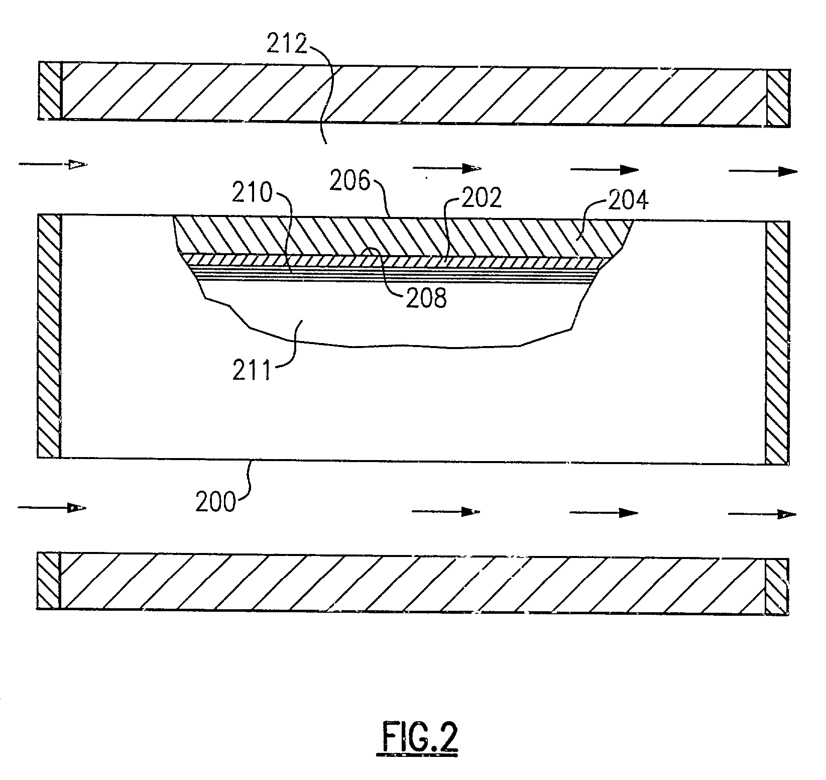
[0045] An osmotic layer or membrane was prepared by coating a thin layer of collodion (cellulose nitrate base polymer) onto the inner surface of a commercial alumina cylindrical tube having an asymmetric pore distribution. This tube is the condenser layer of the present invention and is represented by the reference numeral 200 in FIG. 2. The porous wall of the tube had an inner alpha-alumina capillary pore layer 202, 20 nanometers thick, and an outer gamma-alumina larger pore support layer 204 of gamma alumina 3.times.10.sup.6 nanometers thick. The capillary pore layer had a pore size of 40 Angstrom, and the support layer had a porosity decreasing from about 1.0 micron at the tube outer surface 206 to about 2.times.10.sup.-3 microns at the interface 208 with the capillary layer 202. The thin collodion layer is designated by the reference numeral 210. Prior to coating, the tube had an inner diameter of 0.7 cm, an outer diameter of 1.0 cm...


PUM


Abstract

A humid gas stream is dehumidified by bringing that stream into contact with the front surface of a hydrophilic capillary condenser layer that captures the water and moves it adjacent the rear surface of the capillary layer. An osmotic layer, such as a semi-permeable membrane, is disposed on the rear surface of the condenser layer, and an osmotic fluid having a low concentration of water therein, is disposed adjacent the osmotic layer. An osmotic driving force, resulting from the water concentration gradient across the osmotic layer, transports the condensed water from the condensing layer through the thickness of the osmotic layer and into an osmotic fluid. The osmotic layer also inhibits the osmotic fluid from flowing into the condenser layer.

Description

[0001] This invention relates to conditioning a gas stream, such as air, and especially to the dehumidification of a gas stream.[0002] Conditioning of a gas stream, such as air, generally involves the removal or addition of moisture and the increase or decrease of temperature to make the gas stream suitable for its intended environment. For air conditioning in warm weather, this typically involves dehumidifying and cooling the air to comfortable levels.[0003] Current dehumidification technology is based on the conventional, refrigerant vapor compression cycle (hereinafter referred to as DX technology) or on desiccant substrate capture technology (hereinafter referred to as DS technology). DX technology requires cooling humid supply air, such as the air within a room and / or outside air, to the water vapor condensation point, with external heat rejection on the compression side. This usually requires the supply air to be cooled below comfortable temperatures and, thereafter, either re...

Claims


Application Information

Patent Timeline
IPC IPC(8): B01D53/26F24F3/147
CPCB01D53/268F24F2003/144F24F2003/1435F24F3/147
Inventor KESTEN, ARTHUR S.SATYAPAL, SUNITAFREIHAUT, JAMES D.HAWK, CAROL M.
Owner ARTHUR S KESTEN
Why Eureka
Try Eureka