Optical diffusing plate, optical element and liquid crystal display

a technology of optical elements and optical diffusing plates, applied in the direction of optical elements, polarising elements, instruments, etc., can solve the problems of chromic emission of light, inability to apply to a reflected type liquid crystal display, and difficulty in manufacturing

Inactive Publication Date: 2002-10-03
NITTO DENKO CORP
View PDF0 Cites 10 Cited by
  • Summary
  • Abstract
  • Description
  • Claims
  • Application Information

AI Technical Summary

Problems solved by technology

It is expected using this method that the following conventional problems may be solved; a problem based on a large wavelength dependability of a cholesteric liquid crystal in the conventional absorption loss reduction systems in which a cholesteric liquid crystal layer and a quarter wavelength plate are used, and especially, problems that transmitted light is chromic from oblique direction and that these cannot be applied to a reflected type liquid crystal display etc.
However, in the above-mentioned conventional optical diffusing plate, there were problems of a difficulty in manufacturing, a...

Method used


Image

  • Optical diffusing plate, optical element and liquid crystal display
  • Optical diffusing plate, optical element and liquid crystal display
  • Optical diffusing plate, optical element and liquid crystal display

Examples


example 1

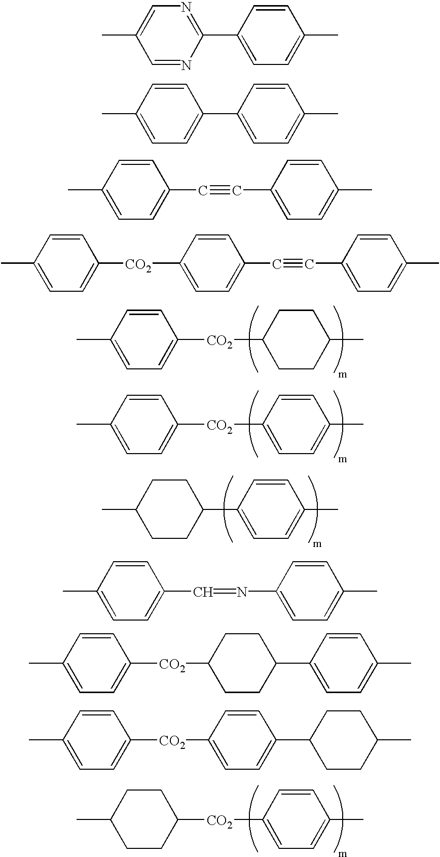
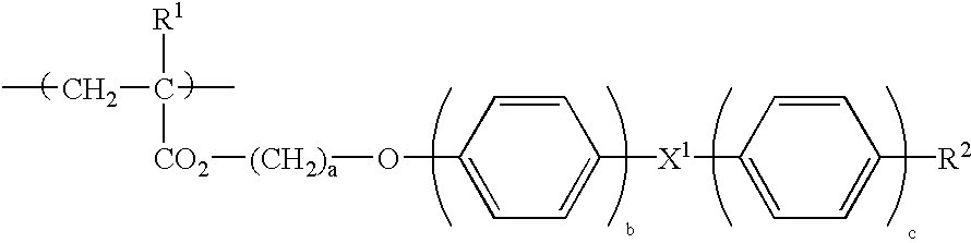
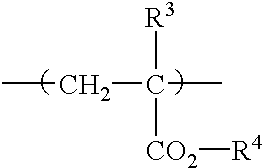
[0079] A 25 weight % toluene solution containing 100 parts of norbornene series resin (brand name Zeonex, by Nihon Zeon Corporation) comprising hydrocarbon as base material polymer of a birefringent stretched film and 6 parts of a side chain type liquid crystal polymer represented by the formula [Formula 5] shown below (where n=35, in molar % of monomer unit, shown in block for convenience, weight average molecular weight: 10000) were mixed together. A film with a thickness of 100 .mu.m was obtained from the mixed solution by casting method. The film obtained was stretched at a stretching ratio of three at 160.degree. C. to obtain an optical diffusing plate comprising a birefringent stretched film that contains the minute domain of the above-mentioned side chain type liquid crystal polymer in a dispersed state.

[0080] [Formula 5] 5

[0081] In the above-mentioned birefringent stretched film, a norbornene series resin forms a film, in which a side chain type liquid crystal polymer is dis...

example 2

[0087] An optical diffusing plate obtained in Example 1 and a commercially available polarizing plate that has 41% of total light transmittance, and 99% of polarizing degree of a transmitted light were adhered through an acrylics series adhesive layer so that the direction of a stretching axis and the transmission axis might correspond, and an optical element was manufactured.

example 3

[0088] A polarizing plate, a TN liquid crystal cell, and the optical element obtained in Example 3 were adhered one by one through an acrylic series adhesive layer on a diffuse reflection plate so that the polarizing plate might be configured at the cell side, and a reflected type liquid crystal display illustrated in FIG. 4 was obtained. In addition, the polarizing plate was configured so that the direction of a transmission axis might correspond with each rubbing direction that meets a liquid crystal cell.

[0089] As a result of investigating brightness in a displaying state with a brightness meter for the liquid crystal display obtained in Example 3, a significant improvement in brightness was confirmed compared with the case where only a polarizing plate was used.


PUM


Abstract

An optical diffusing plate that gives a anisotropic scattering of a linearly polarized light and has an excellent diffusion property in a scattering direction, and that is suitable for improving visibility, brightness of a liquid crystal display, comprising a birefringent film and a minute domain with a birefringent characteristic different from the birefringent film in a dispersed state in the birefringent film, the birefringent film comprises a birefringent stretched film, and the minute domain comprises a positive uniaxial liquid crystal polymer, wherein a length of the minute domain in a direction of stretching axis is longer than a length in a direction orthogonal to the stretching axis, and the liquid crystal polymer is aligned perpendicularly to a stretching axis of the birefringent stretched film.

Description

[0001] 1. Field of the Invention[0002] The present invention relates to an optical diffusing plate that gives an anisotropic scattering of a linearly polarized light and has an excellent diffusion property in a scattering direction, and that is suitable for improving visibility, brightness etc. of a liquid crystal display etc. Moreover, the present invention relates to an optical element using the optical diffusing plate concerned.[0003] 2. Description of the Prior Art[0004] Conventionally, an optical diffusing plate designed so that anisotropic scattering might be given to a linearly polarized light by making a domain with a refractive index anisotropy contained in a dispersed state in a base material has been known. As the optical diffusing plate concerned; an optical diffusing plate that comprises a combination of a thermoplastic resin and a low molecular weight liquid crystal, that comprises a combination of a low molecular weight liquid crystal and a photo-curable low molecular...

Claims


Application Information

Patent Timeline
IPC IPC(8): G02B5/02G02B5/30G02F1/1335G02F1/13363
CPCG02B5/0236G02F1/133528G02B5/3016G02B5/0257G02B5/02
Inventor NAKANISHI, SADAHIROMIYATAKE, MINORUNAKANO, SHUSAKUMOCHIZUKI, AMANE
Owner NITTO DENKO CORP
Why Eureka
Try Eureka