Vapor-liquid contactor, cryogenic air separation unit and method of gas separation

Inactive Publication Date: 2002-10-31
TAIYO NIPPON SANSO CORP
View PDF0 Cites 20 Cited by
  • Summary
  • Abstract
  • Description
  • Claims
  • Application Information

AI Technical Summary

Problems solved by technology

Further, it may promote a dispersion of the liquid by providing corrugations and/or unevennesses and/or holes on the surface of the metal sheet.
However, there are disadvantages in the above packed column type of vapor-liquid contactor in that a higher column should be provided and costs for the production and construction of an apparatus are high, when compared to the siev

Method used


Image

  • Vapor-liquid contactor, cryogenic air separation unit and method of gas separation
  • Vapor-liquid contactor, cryogenic air separation unit and method of gas separation
  • Vapor-liquid contactor, cryogenic air separation unit and method of gas separation

Examples


Example

EXAMPLE 1

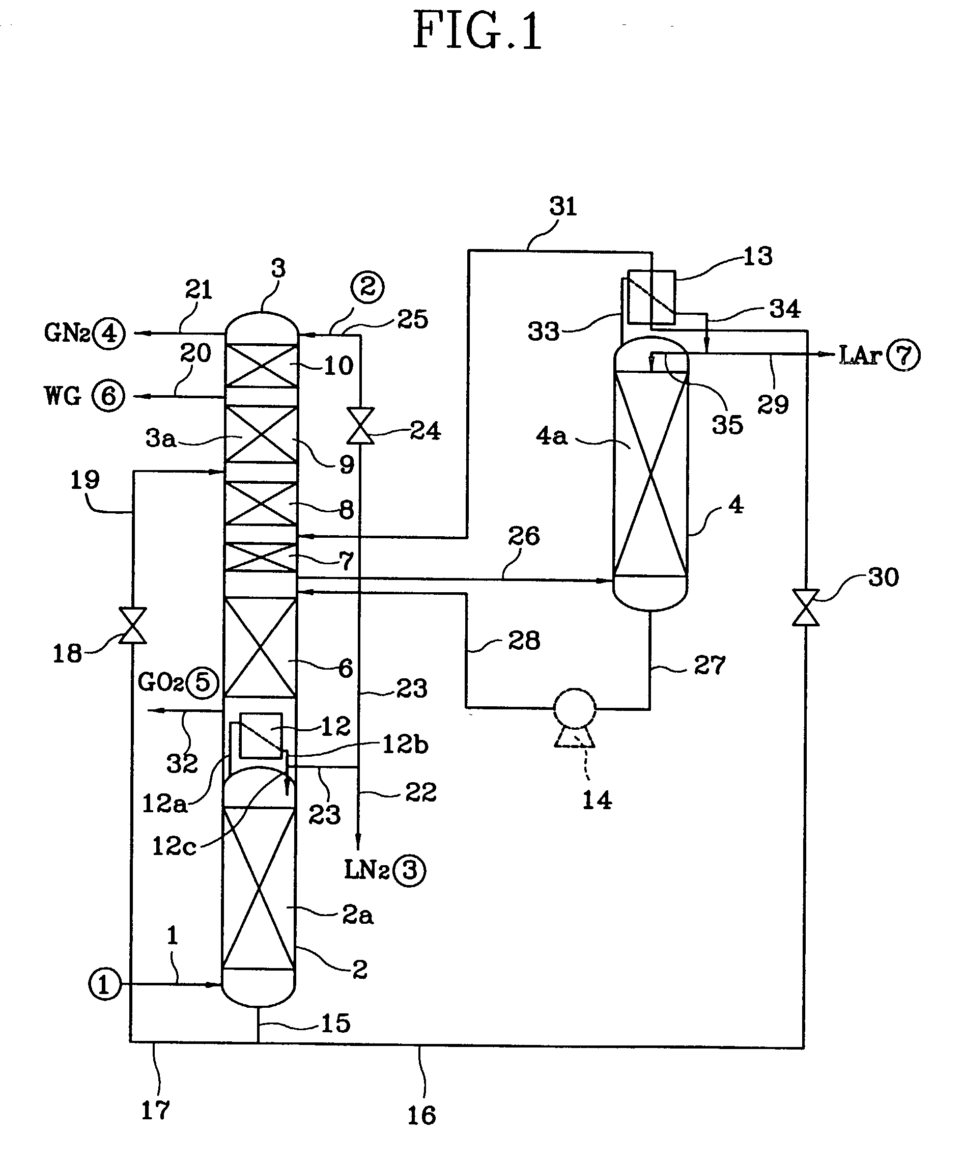
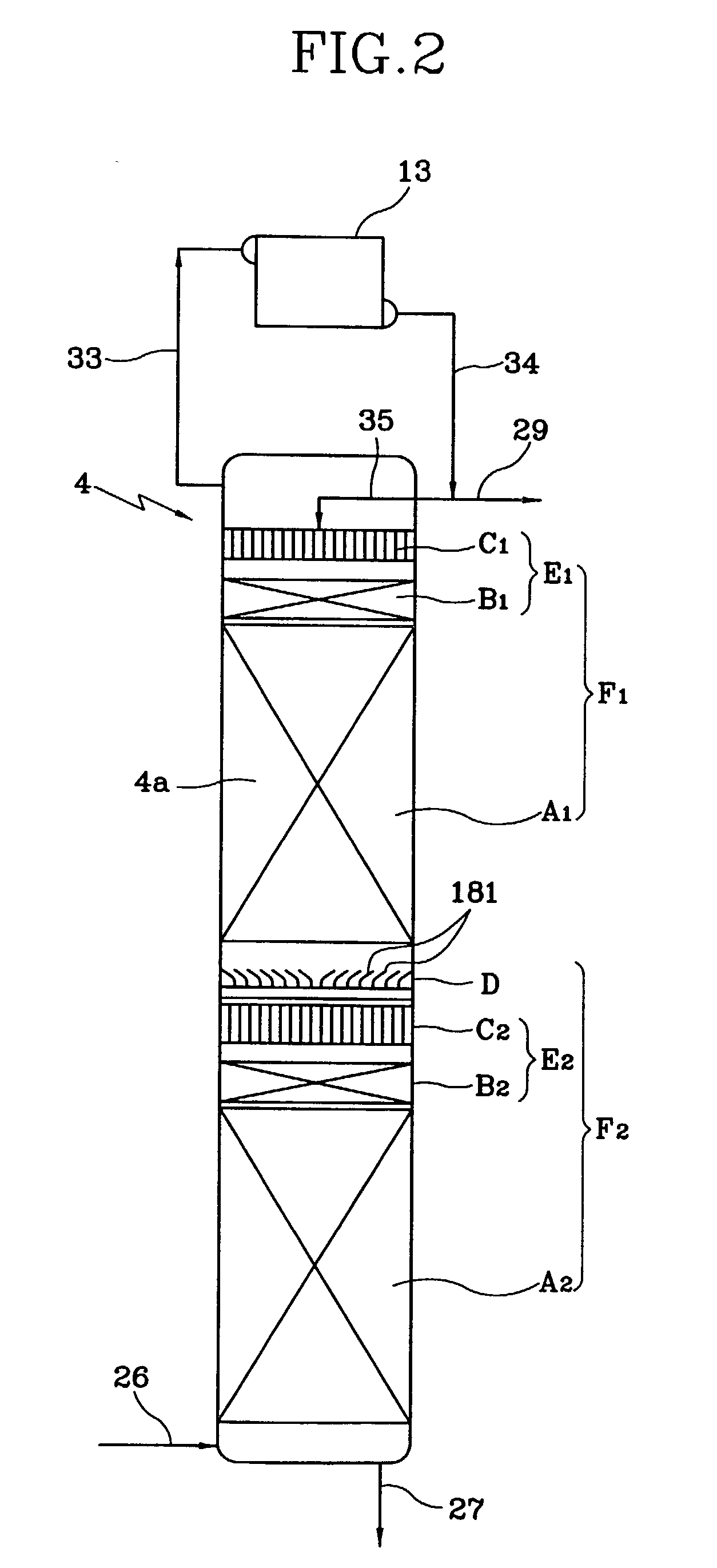
[0184] The computer simulation of a distillation operation using a cryogenic air separation unit shown in FIG. 1 was carried out. The vapor-liquid contactor 2a, 4a in a high pressure column 2 and a crude argon column 4 was assumed to have a liquid distributor E.sub.1, a non-promoting-fluid dispersion type structured packing A.sub.1, a liquid collector D, a liquid distributor E.sub.2 and a non-promoting-fluid dispersion type structured packing A.sub.2 along the bottom from the peak of the column, as shown in FIG. 2.

[0185] Further, in each section 6.about.9 of the vapor-liquid contactor 3a, the liquid collector and vapor-liquid contactor F.sub.2 was used, and in the section 10, the liquid collector and vapor-liquid contactor F.sub.1 was used.

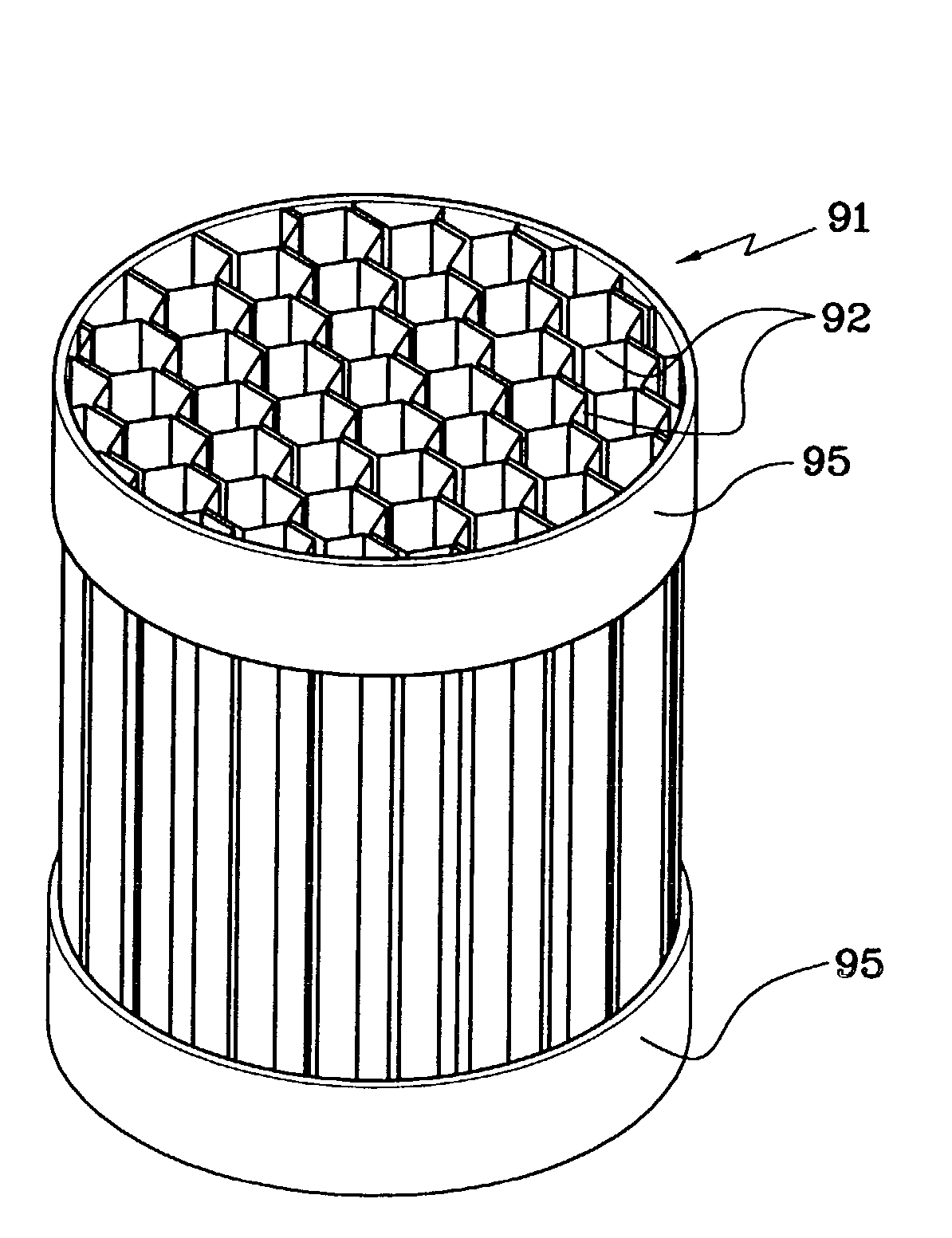
[0186] As the non-promoting-fluid dispersion type structured packing A.sub.1, A.sub.2, a structured packing 91 was used. As the self-promoting-fluid dispersion type structured packing B.sub.1, B.sub.2, a structured packing 71 was used. As...

Example

Comparative Example 1

[0188] In the vapor-liquid contactor 4a, a distillation operation was carried out in the same manner as Example 1, using the same apparatus as shown in FIG. 1 except that the self-promoting-fluid dispersion type structured packing of the same area was used instead of the non-promoting-fluid dispersion type structured packing A.sub.1, A.sub.2. The results are shown with a dotted line in FIG. 27.

[0189] In a vapor-liquid contactor 4a shown in FIG. 27, by using the non-promoting-fluid dispersion type structured packing A.sub.1, A.sub.2, the required packing height accounts for 60 percent when compared to the case when the self-promoting-fluid dispersion type structured packing is used.

[0190] Next, to compare a pressure loss when the non-promoting-fluid-dispe-rsion type structured packing is used as a packing and when the self-promoting-fluid-dispersion type structured packing is used, the following experiments were carried out.

Example

EXAMPLE 2

[0191] The following experiments were carried out by using a distillation column which is a vapor-liquid contactor shown in FIG. 28. This distillation column (inner diameter 208 mm, prepared from transparent vinyl chloride) includes a rough dispersion part C.sub.3, a minute distribution part B.sub.3, and a non-promoting-fluid-distribution type structured packing A.sub.3 over the bottom portion from the top portion of the column.

[0192] As the rough distribution part C.sub.3, the same part as shown in FIG. 4 was used. As the minute distribution part B.sub.3, the self-promoting-fluid dispersion type structured packing 2 elements denoted by the reference number 87 having a specific surface area of 500 m.sup.2 / m.sup.3 and a height of 100 mm, the parallel plane plate group 85 (height 50 mm) as shown in FIG. 26, and a parallel plane sheet group 86 (height 50 mm) as shown in FIG. 27 were used in the order from the top portion.

[0193] In this case, two parallel plane sheet groups 85a...


PUM

PropertyMeasurementUnit
Lengthaaaaaaaaaa
Pressureaaaaaaaaaa
Speedaaaaaaaaaa

Abstract

In an vapor-liquid contactor 4a for flowing down a liquid along the surface of a packing and contacting said liquid with the vapor while ascending the vapor, the improvement being characterized in that said packing is a non-promoting-fluid-dispersion type structured packing A1, A2 in which various types of thin sheets or tubes for determining the flow direction of the above liquid or vapor is laminated and arranged in the perpendicular direction, and said contactor includes at least one fluid distribution unit E1, E2 formed of a rough distribution part C1, C2 to distribute the liquid roughly and a minute distribution part B1, B2 to distribute the liquid minutely and equally.

Description

[0001] The present invention relates to a vapor-liquid contactor adapted to perform a vapor-liquid contact to thereafter separate gas mixture under a cryogenic distillation, and more particularly to a vapor-liquid contactor for use in the cryogenic air separation unit for carrying out a cryogenic separation of nitrogen, oxygen, argon from air, to a cryogenic air separation unit using the vapor-liquid contactor, and to a method of gas separation using the vapor-liquid contactor.TECHNICAL BACKGROUND[0002] A distillation column used in a cryogenic air separation unit, etc. includes a packed column, a sieve tray column and the like. Among them, a packed column has an advantage of a low pressure loss (pressure drop) and a low operation cost with comparison to a sieve tray column. Further, the packed column has several advantages in that it can increase a relative volatility between each components of air by setting a low operation pressure according to its low pressure loss; the length o...

Claims


Application Information

Patent Timeline
IPC IPC(8): B01D3/20B01J19/32F25J3/04
CPCB01D3/20F25J3/04678B01J2219/3221B01J2219/32213B01J2219/3222B01J2219/32227B01J2219/32244B01J2219/32248B01J2219/32258B01J2219/32262B01J2219/32272B01J2219/32279B01J2219/32286B01J2219/32296B01J2219/32408B01J2219/32483F25J3/04909F25J3/04927F25J2200/04F25J2200/90F25J2215/58F25J2290/10Y10S261/72F25J3/04412B01J19/32F25J2250/02
Inventor HAYASHIDA, SHIGERUKIHARA, HITOSHIKAWAKAMI, HIROSHI
Owner TAIYO NIPPON SANSO CORP
Why Eureka
Try Eureka