Method of reading stored data and semiconductor memory device

a technology of memory device and stored data, which is applied in the direction of semiconductor devices, digital storage, instruments, etc., can solve the problems of degrading the quality of memory, increasing the number of elements, and falling the degree of integration

Inactive Publication Date: 2002-10-31
SONY CORP
View PDF0 Cites 29 Cited by
  • Summary
  • Abstract
  • Description
  • Claims
  • Application Information

AI Technical Summary

Problems solved by technology

When the SNM becomes small, the probability of destruction of the stored data of the memory cell due to noise rises, so there is the disadvantage of a degradation of the quality as a memory.
Accordingly, where the power supply voltage falls, the six-transistor type SRAM cell is frequently

Method used


Image

  • Method of reading stored data and semiconductor memory device
  • Method of reading stored data and semiconductor memory device
  • Method of reading stored data and semiconductor memory device

Examples


first embodiment

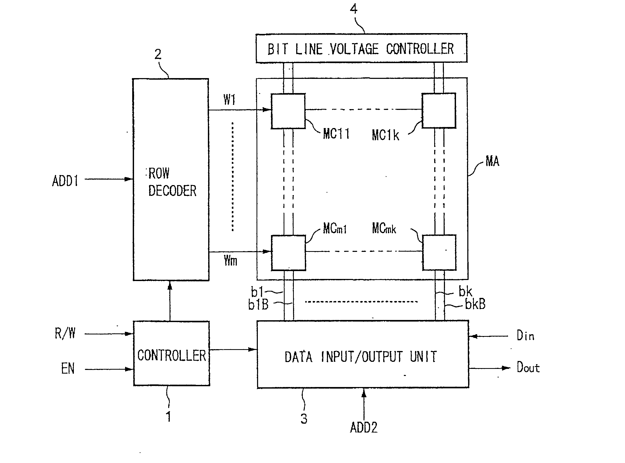
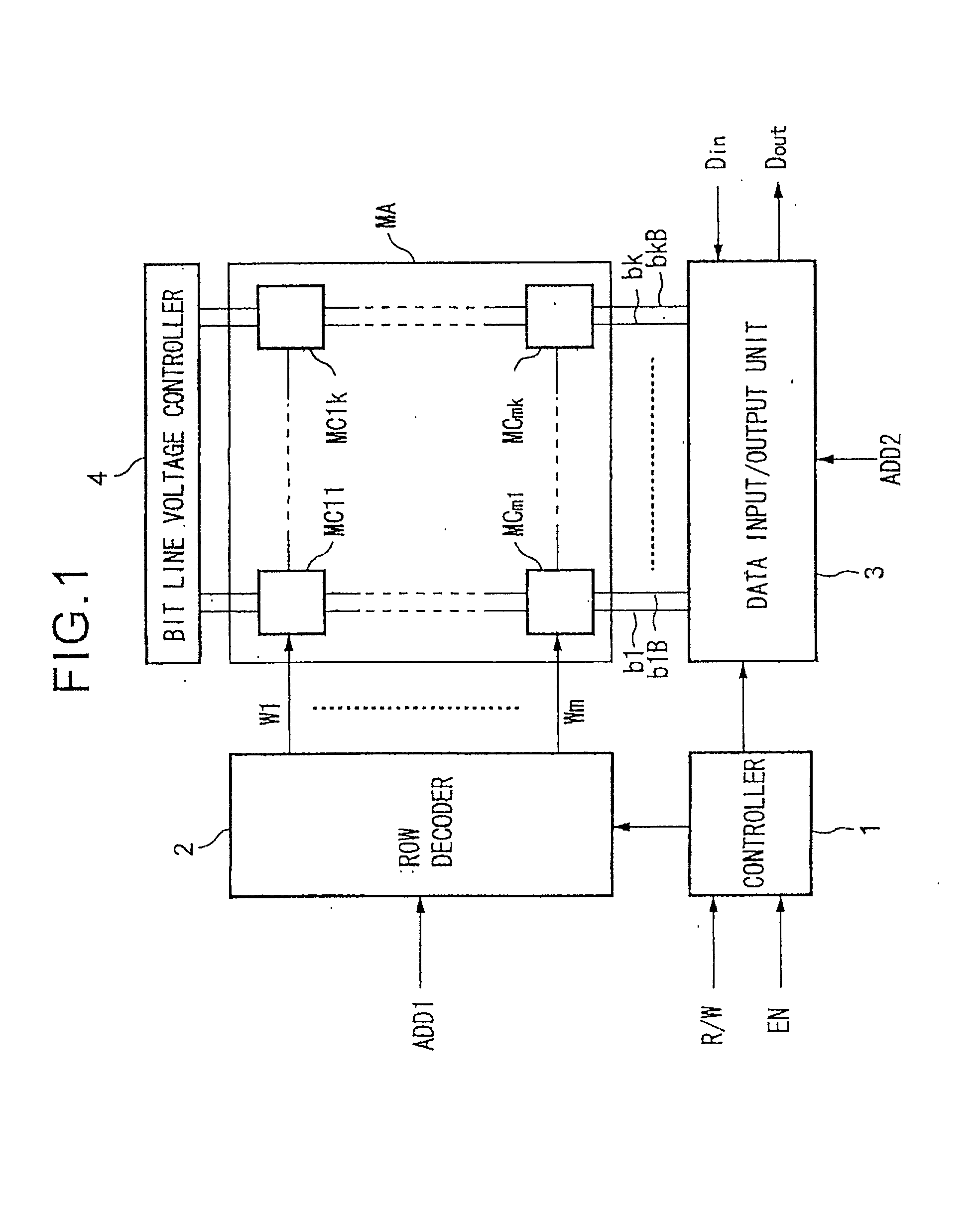
[0161] FIG. 1 is a schematic view of an example of the configuration of a SRAM according to the present invention. The SRAM shown in FIG. 1 includes a controller 1, row decoder 2, data input / output unit 3, bit line voltage controller 4, and memory cell array MA. Also, the memory cell array MA includes a memory cell MC11 to memory cell MCmk.

[0162] When an enable signal EN is set to an active state, the controller 1 outputs various control signals for the read or write operation of data selected in accordance with a selection signal R / W to the row decoder 2, data input / output unit 3, and bit line voltage controller 4 to control the write or read operation of the data with respect to the memory cell array MA.

[0163] The row decoder 2 decodes address data ADD1 in accordance with the control signal from the controller 1 at the time of reading or writing of the data and selects and activates one of a word line W1 to word line Wm connected to the memory cell MC11 to the memory cell MCmk of ...

second embodiment

[0228] Next, an explanation will be made of a second embodiment of the present invention.

[0229] FIG. 8 is a schematic block diagram of an example of the configuration of an associative memory according to the second embodiment of the present invention.

[0230] The associative memory shown in FIG. 8 has an address controller 11, CAM cell array 12, data input / output unit 13, search result register 14, priority encoder 15, address power supply unit 16, and data power supply unit 17.

[0231] The address controller 11 receives an address data EX_ADD input from the outside or an address data M_ADD of the search result selected at the priority encoder, selects the word line of the CAM cell array 12 corresponding to the input address data, and activates the selected word line at the time of writing and the time of reading of the data. In the period for holding the stored data and at the time of the match search explained later, all word lines are deactivated, and access from the bit lines to th...

third embodiment

[0284] Next, an explanation will be made of a third embodiment of the present invention. The difference between the second embodiment and the third embodiment resides in the point that the configuration of the logical circuit portion for outputting the match search result to the mismatch detection line ML in the CAM cell is different.

[0285] Note that, the overall configuration of the associative memory is similar to that of FIG. 8, so the explanation is omitted, and just the binary CAM cell will be explained by referring to FIG. 11.

[0286] FIG. 11 is a circuit diagram showing the example of the configuration of the binary CAM cell according to the third embodiment of the present invention.

[0287] In FIG. 11, notation Qp203 and notation Qp204 designate p-type MOS transistors, notation Qn201, notation Qn202, and notation Qn205 to notation Qn207 designate n-type MOS transistors, notation WL designates the word line, notation BL and notation / BL designate the bit line pair, and notation ML...


PUM


Abstract

A method of reading stored data in a semiconductor memory device able to suppress the reduction in the static noise margin accompanying a voltage drop of a power supply voltage, and able to improve the degree of integration of the circuit, that is, a method of reading stored data of a semiconductor memory device which has a first storage node and a second storage node, a first transistor having a control terminal connected to the first storage node and having a pair of input/output terminals connected between the second storage node and a reference potential, a second transistor having a control terminal connected to the second storage node and having a pair of input/output terminals connected between the first storage node and the reference potential, a third transistor having a pair of input/output terminals connected between the first storage node and a first bit line and having a control terminal connected to a word line, and a fourth transistor having a pair of input/output terminals connected between the second storage node and a second bit line and having a control terminal connected to the word line, comprising the steps of applying a first voltage to the first bit line and the second bit line in a period for holding the stored data, and activating the word line and applying a second voltage higher than the first voltage to the first bit line and the second bit line at the time of reading the stored data, and a semiconductor memory device using the same.

Description

[0001] 1. Field of the Invention[0002] The present invention relates to a method of reading stored data and a semiconductor memory device, more particularly relates to a method of reading data stored in a semiconductor memory device including a static type random access memory (RAM) and such a semiconductor memory device and to a semiconductor memory device including a static type content addressable memory (CAM).[0003] 2. Description of the Related Art[0004] First, an explanation will be made of a static RAM (SRAM) and a CAM having a SRAM type memory circuit.SRAM[0005] SRAMs enable high speed read and write operations and, at the same time, eliminate the need for a refresh operation of the stored data as with a dynamic RAM (DRAM) and enable streamlining of peripheral circuits. Due to these advantages, they are being widely used as cache memories, memories of portable terminals, and other relatively small capacity memory devices for which high speed operation and streamlining are re...

Claims


Application Information

Patent Timeline
IPC IPC(8): G11C7/22G11C11/41G11C11/418G11C11/412G11C11/419G11C15/04H01L21/8244H01L27/11
CPCG11C7/22G11C15/04G11C11/419G11C11/412
Inventor KASAI, GENFURUMI, KOJI
Owner SONY CORP
Why Eureka
Try Eureka