

Electrolytic phosphate chemical treatment method
Inactive Publication Date: 2002-11-07
DENSO CORP
View PDF2 Cites 5 Cited by
- Summary
- Abstract
- Description
- Claims
- Application Information
AI Technical Summary
Benefits of technology
[0026] Although the inventor of the present invention devised a countermeasure for preventing an electrolytic reaction in the solution phase in an invention disclosed in previously disclosed Japanese Unexamined Patent Publication No. 2000-234200, this could not always be said to be adequate with respect to reliably preventing the solution phase reaction and limiting to only a reaction of a metal surface. Therefore, the problem to be solved by the present invention is to improve the level of control of an electrolytic phosphate chemical treatment reaction as an electrolytic surface treatment in the invention disclosed in Japanese Unexamined Patent Publication No. 2000-234200. Namely, the object of the present invention is to establish a means for further improving the reaction efficiency on a metal surface (interface) by preventing the reaction in the solution phase to reliably prevent sludge formation during continuous treatment.
Problems solved by technology
However, studies regarding the inherent prior art of non-electrolytic phosphate chemical treatment were not always adequate.
However, when this method is used to carry out treatment continuously, it was found that sludge forms depending on the treatment conditions.
However, in the case of performing treatment continuously, it was found to be difficult to maintain "not allowing the components in solution to react at a location other than the electrode surface" with only the accommodations made in the above-mentioned invention of Japanese Unexamined Patent Publication No. 2000-234200.
Namely, in Japanese Unexamined Patent Publication No. 2000-234200, although the treatment bath is constantly filtered and circulated during electrolytic treatment, it was found that solids (sludge) are trapped by the filter at that time.
As has been described above, the prior art relating to electrolytic phosphate chemical treatment was inadequate with respect to not allowing the reaction of solution phase components (not allowing the formation of sludge), which is the basis of electrolytic surface treatment technology.
For this reason, the electrolytic phosphate chemical treatment technology of the prior art was inadequate as an electrolytic surface treatment technology.
In the electrolytic phosphate chemical treatment of the prior art, the above approach of preventing reaction in the solution phase was not given adequate consideration at the practical level.
Namely, whether the nitrogen oxide gas generated is in the form of N.sub.2O.sub.4 and NO.sub.2 or NO results in a considerable difference in the conditions by which the gas is removed from the treatment bath.
However, if the gas that is generated contains N.sub.2O.sub.4 and NO.sub.2, that gas cannot be easily removed from the treatment bath, and it is therefore presumed that the reaction efficiency at the electrode surface (interface) would decrease.
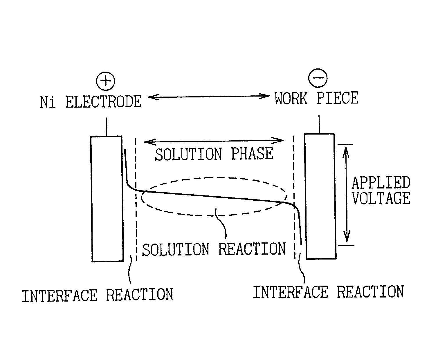
However, conventional non-electrolytic phosphate chemical treatment forms a film by using a solution phase reaction (see FIG. 8).
Consequently, a bath consisting primarily of H.sub.3PO.sub.4 at pH 2.5 or lower does not allow the formation of a film in non-electrolytic treatment.
Furthermore, in the case of using an insoluble anode material in cathodic electrolysis, the metal ion dissolution-precipitation reaction of (i) is limited to a precipitation reaction only.
The decrease in reactable components results in a decrease in reactivity and a decrease in the ORP of the treatment bath.
Consequently, when replenishing chemical is added, it tends to act in a direction that lowers the pH of the treatment bath, which is turn causes an increase in the ORP of the treatment bath.
In the pressurized state, it is difficult for gases dissolved in the treatment bath to escape from solution.
Such a change in the treatment bath is harmful with respect to the stability of the treatment bath.
Method used
View moreImage
Smart ImageViewing Examples

Examples
examples 1-3
[Explanation of Examples 1-3 and Comparative Examples 1-2 and Analysis of Experiment Results]
example 1
[0145] Example 1 is the standard method of the present invention. The amount of Fe electrolysis is controlled and the standard chemical is used. For this reason, there is no formation of sludge in the treatment bath even after standing.
example 2
[0146] Example 2 is an example of the present invention in the case of using a replenishing chemical containing Fe ions.
Login to View More PUM
| Property | Measurement | Unit |
|---|---|---|
| Electric potential / voltage | aaaaa | aaaaa |
| Electric potential / voltage | aaaaa | aaaaa |
| Electric potential / voltage | aaaaa | aaaaa |
Abstract
The object of the present invention is to provide an electrolytic phosphate chemical treatment method capable of improving the reaction efficiency on a metal surface (interface) by preventing the reaction in the solution phase so as to reliably prevent sludge formation during continuous treatment. The present invention relates to a method of forming a film composed of a phosphate compound and a metal on the surface of an article to be treated by performing electrolytic treatment on a metal material article to be treated in a phosphate chemical treatment bath by contacting said metal material having electrical conductivity with said phosphate chemical treatment bath containing phosphate ions and phosphoric acid, nitrate ions, metal ions that form a complex with phosphate ions in said phosphate chemical treatment bath, and metal ions for which the dissolution-precipitation equilibrium potential at which ions dissolved in said phosphate chemical treatment bath are reduced and precipitate as metal is equal to or greater than -830 mV, which is the cathodic reaction decomposition potential of the solvent in the form of water when indicated as the hydrogen standard electrode potential, and is substantially free of metal ions other than those which are a component of the film; wherein the ORP (oxidation-reduction potential) of said phosphate chemical treatment bath (indicated as the potential relative to a standard hydrogen electrode) is maintained at equal to or greater than 700 mV.
Description
[0001] 1. Field of the Invention[0002] The present invention relates to surface treatment of a metal, and more particularly, to surface treatment of a metal using a phosphate chemical film.[0003] 2. Description of the Related Art[0004] To begin with, if phosphate chemical treatment technology were to be divided into electrolytic treatment and non-electrolytic treatment, electrolytic treatment would be a new technology while non-electrolytic treatment would be a conventional technology. Although the reaction of phosphate chemical treatment is an electrochemical reaction for both non-electrolytic treatment and electrolytic treatment, the contents of that reaction are quite different.[0005] The inventor of the present invention previously filed a patent relating to electrolytic phosphate chemical treatment (Japanese Unexamined Patent Publication No. 2000-234200). At the time of the previous filing, a study was conducted relating to electrolytic phosphate chemical treatment of the prior...
Claims
Login to View More Application Information
Patent Timeline
 IPC IPC(8): C25D11/36C25D21/04C25D21/12C25D21/14C25D21/16
CPCC25D11/36C25D21/14C25D21/12C25D21/04
InventorMATSUDA, SHIGEKINISHIYA, SHIN
OwnerDENSO CORP