Hydrocarbon gas processing

a technology of hydrocarbon gas and processing equipment, applied in the direction of liquefaction, gaseous mixture working up, lighting and heating equipment, etc., can solve the problem of not having the means available to reduce the power consumption of compressors

Inactive Publication Date: 2002-11-14
ELCOR CORP
View PDF0 Cites 116 Cited by
  • Summary
  • Abstract
  • Description
  • Claims
  • Application Information

AI Technical Summary

Problems solved by technology

Unfortunately, this is not advisable in this instance because of the detrimental effect on distillation performance in deethanizer 17 that would result from the higher operating pressure.
As a result, the operating pressure of deethanizer 17 should not be raised above the value shown ...

Method used


Image

  • Hydrocarbon gas processing
  • Hydrocarbon gas processing
  • Hydrocarbon gas processing

Examples


example 2

[0061] FIG. 3 represents the preferred embodiment of the present invention for the temperature and pressure conditions shown because it typically provides the simplest plant arrangement for a given C.sub.3 component recovery level. A slightly more complex design that maintains the same C.sub.3 component recovery with lower utility consumption can be achieved using another embodiment of the present invention as illustrated in the FIG. 4 process. The feed gas composition and conditions considered in the process presented in FIG. 4 are the same as those in FIGS. 1 and 3. Accordingly, FIG. 4 can be compared with the FIG. 1 process to illustrate the advantages of the present invention, and can likewise be compared to the embodiment displayed in FIG. 3.

[0062] In the simulation of the FIG. 4 process, the feed gas cooling and expansion scheme is much the same as that used in FIG. 3. The difference lies in the manner in which the vapor distillation stream 36 leaving the overhead of deethaniz...

example 3

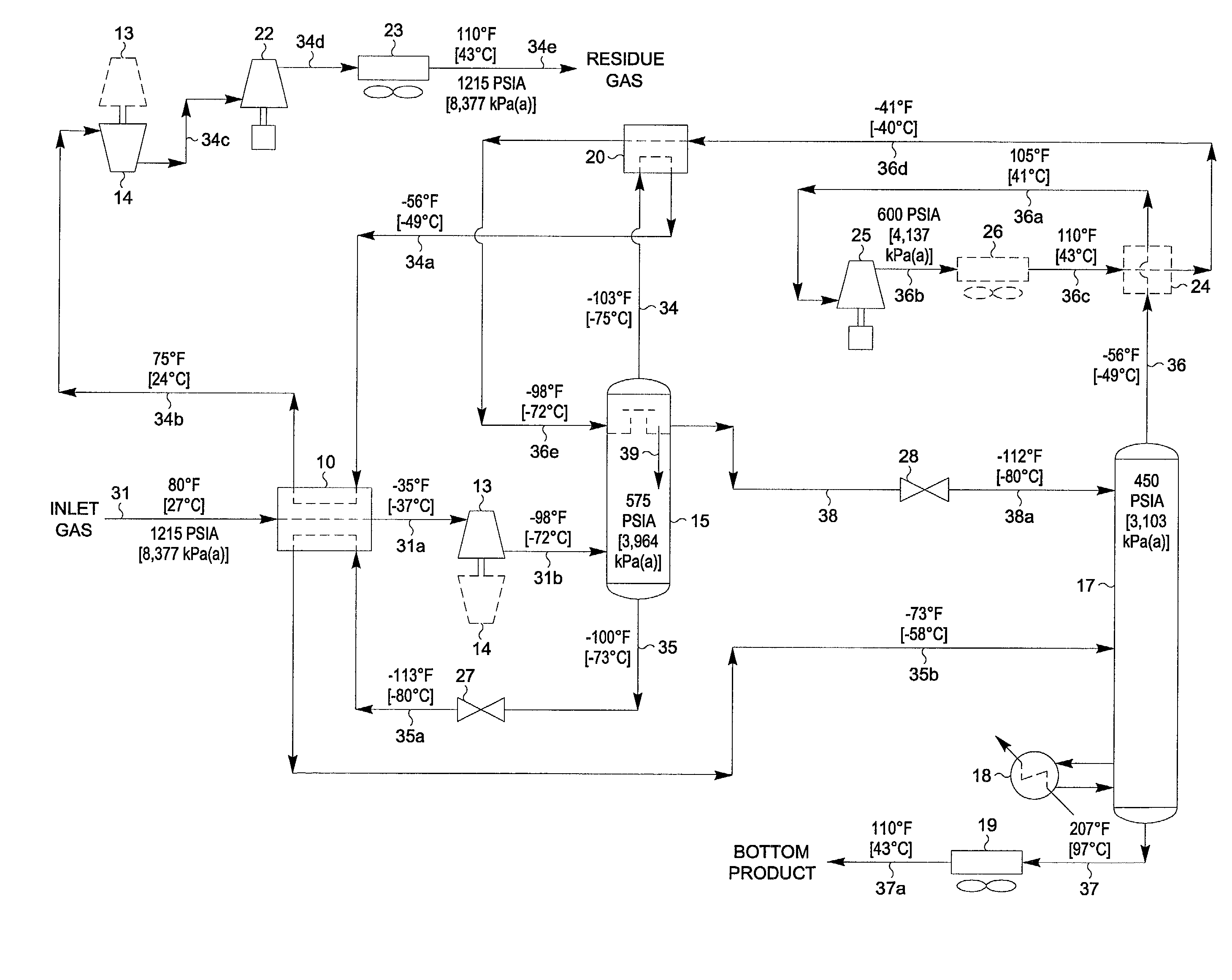
[0068] A third embodiment of the present invention is shown in FIG. 5, wherein a different method of implementing the second mechanical-compression refrigeration cycle is applied to the present invention. The feed gas composition and conditions considered in the process illustrated in FIG. 5 are the same as those in FIGS. 1, 3, and 4. Accordingly, FIG. 5 can be compared with the FIG. 1 process to illustrate the advantages of the present invention, and can likewise be compared to the embodiments displayed in FIGS. 3 and 4.

[0069] In the simulation of the FIG. 5 process, inlet gas enters the plant at 80.degree. F. [27.degree. C.] and 1215 psia [8,377 kPa(a)] as stream 31. The feed stream 31 is cooled in exchanger 10 by heat exchange with cool residue gas at -70.degree. F. [-57.degree. C.] (stream 34a), with cool vapor at -49.degree. F. [-45.degree. C.] (stream 41a), and with separator / absorber liquids at 112.degree. F. [-80.degree. C.] (stream 35a). The cooled stre 31a (a dense-phase f...

example 4

[0079] A slightly more complex design than the FIG. 5 embodiment that maintains the same C.sub.3 component recovery with lower utility consumption can be achieved using another embodiment of the present invention as illustrated in the FIG. 6 process. The feed gas composition and conditions considered in the process presented in FIG. 6 are the same as those in FIGS. 1 and 5. Accordingly, FIG. 6 can be compared with the FIG. 1 process to illustrate the advantages of the present invention, and can likewise be compared to the embodiment displayed in FIG. 5.

[0080] In the simulation of the FIG. 6 process, the feed gas cooling and expansion scheme is much the same as that used in FIG. 5. The difference lies in the manner in which the vapor distillation stream 36 leaving the overhead of deethanizer 17 is used to generate reflux for deethanizer 17 and separator / absorber 15. Referring to FIG. 6, the deethanizer overhead vapor (stream 36) exits deethanizer 17 at -39.degree. F. [-40.degree. C.]...


PUM


Abstract

A process for the recovery of propane, propylene and heavier hydrocarbon components from a hydrocarbon gas stream is disclosed. The stream is cooled and/or expanded to partially condense it, then separated to provide a first vapor stream. The first vapor stream is directed into a contacting device whereby vapors and liquids are formed. The liquids are directed to a distillation column operating at lower pressure wherein a second vapor stream is separated to recover a product containing the major portion of the C3 components and heavier hydrocarbon components. The second vapor stream is directed into heat exchange relation with the vapors to cool the second vapor stream and condense at least a part of it, forming a condensed stream. At least a portion of the condensed stream is directed to the contacting device to intimately contact the first vapor stream; the remaining portion (if any) of the condensed stream can be supplied to the distillation column as its top feed. The quantities and temperatures of the feeds to the contacting device and the distillation column are effective to maintain the overhead temperatures of the contacting device and the distillation column at temperatures whereby the major portion of the desired components is recovered.

Description

[0001] This invention relates to a process for the separation of a gas containing hydrocarbons. The applicants claim the benefits under Title 35, United States Code, Section 119(e) of prior United States provisional application Serial No. 60 / 225,260 which was filed on Aug. 15, 2000.[0002] Propylene, propane, and / or heavier hydrocarbons can be recovered from a variety of gases, such as natural gas, refinery gas, and synthetic gas streams obtained from other hydrocarbon materials such as coal, crude oil, naphtha, oil shale, tar sands, and lignite. Natural gas usually has a major proportion of methane and ethane, i.e., methane and ethane together comprise at least 50 mole percent of the gas. The gas also contains relatively lesser amounts of heavier hydrocarbons such as propane, butanes, pentanes and the like, as well as hydrogen, nitrogen, carbon dioxide and other gases.[0003] The present invention is generally concerned with the recovery of propylene, propane and heavier hydrocarbons...

Claims


Application Information

Patent Timeline
IPC IPC(8): C07C7/00C10G5/06C10G70/04F25J3/02
CPCC07C7/005F25J2270/90C10G70/04F25J3/0209F25J3/0219F25J3/0233F25J3/0242F25J2200/04F25J2200/70F25J2200/74F25J2200/76F25J2200/78F25J2205/02F25J2205/04F25J2210/12F25J2230/60F25J2235/60F25J2240/02F25J2270/02C10G5/06
Inventor WILKINSON, JOHN D.LYNCH, JOE T.HUDSON, HANK M.
Owner ELCOR CORP
Why Eureka
Try Eureka