Magnesium calcium thioaluminate phosphor

a technology phosphor, which is applied in the field of magnesium calcium thioaluminate phosphor, can solve the problems of low energy efficiency and correspondingly high power consumption of the display, and the phosphor is more difficult to deposit as a thin film for electroluminescent displays, and it is not possible to compensate for the lower deposition temperatur

Inactive Publication Date: 2002-12-19
IFIRE IP CORP
View PDF0 Cites 6 Cited by
  • Summary
  • Abstract
  • Description
  • Claims
  • Application Information

AI Technical Summary

Problems solved by technology

However, because the spectral emission from this phosphor material is relatively wide, ranging from red to green, there is a substantial loss of luminance as the light passes through the filter, resulting in a relatively low energy efficiency and correspondingly high power consumption for the display.
However, this phosphor is more difficult to deposit as a thin film for electroluminescent displays.
If the deposition temperature must be lowered due to problems of stability of the deposition materials at higher temperatures, it may not be possible to compensate for the lower deposition temperature by use of a higher annealing temperature.
In full colour electroluminescent displays with a thick film dielectric employing a patterned phosphor structure, the maximum temperature tolerated by photoresist materials used in the patterning process may limit the deposition temperature.

Method used


Image

  • Magnesium calcium thioaluminate phosphor
  • Magnesium calcium thioaluminate phosphor
  • Magnesium calcium thioaluminate phosphor

Examples


example ii

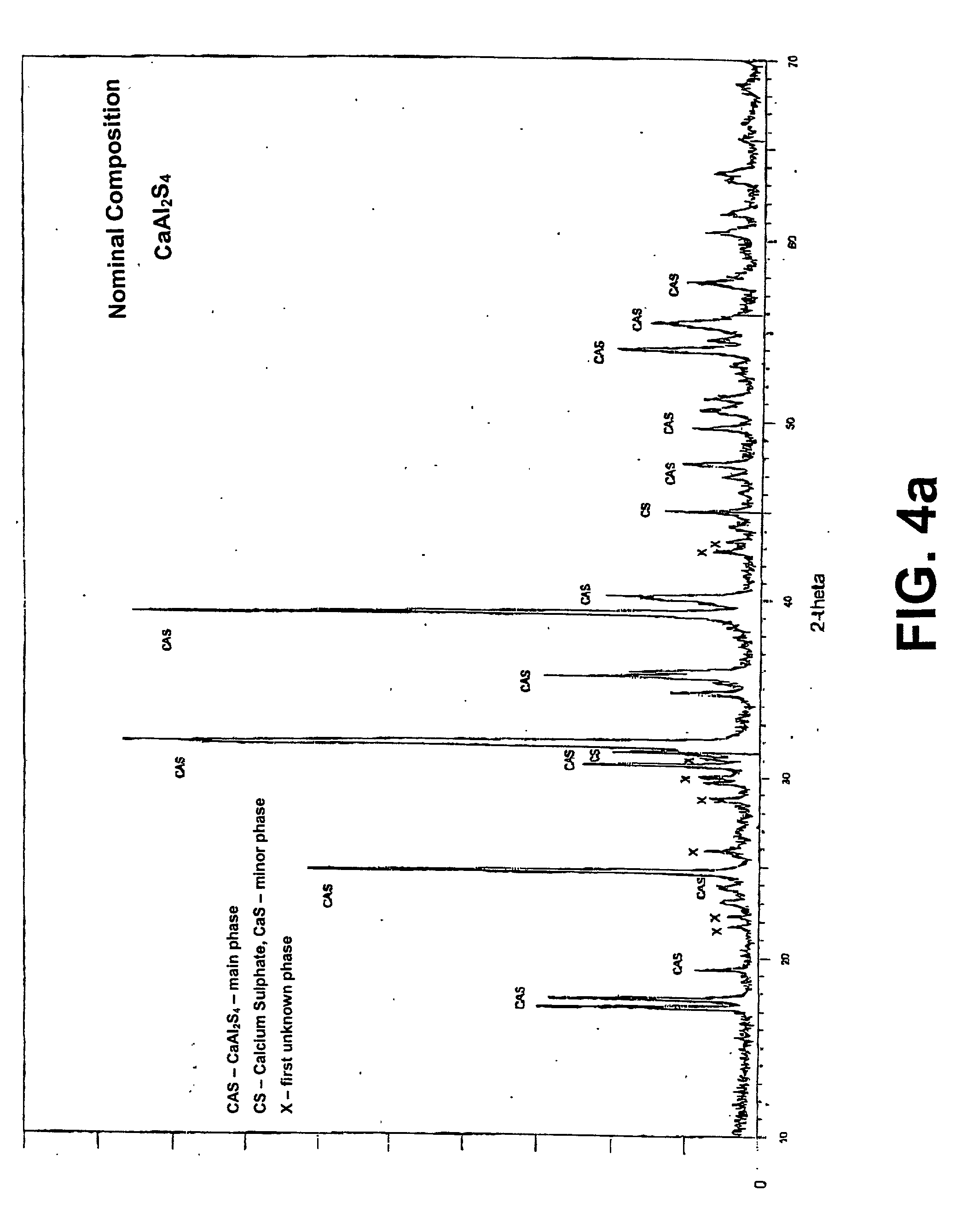
[0056] The phosphors prepared as in Example I were subjected to x-ray diffraction analysis. The X-ray diffraction patterns are shown in FIGS. 4a through 4h. In addition, the patterns are shown on a reduced scale with a common x-axis in FIG. 5.

[0057] The dominant diffraction pattern for each phosphor is that for calcium thioaluminate.

[0058] The diffraction patterns for the phosphors with x=0.00 i.e. no magnesium, and x=0.01 i.e. 1 atomic percent of magnesium, also show diffraction peaks for calcium sulphide, with less calcium sulfide in the latter sample (1 atomic percent magnesium) and a first unidentified crystal phase.

[0059] The diffraction pattern for the phosphor with x=0.05 does not show the peak for calcium sulphide, but does show the same unidentified crystal phase (first unidentified crystal phase) as the phosphor with x=0.01.

[0060] The diffraction pattern for the phosphor with x=0.10 does not show a peak for calcium sulfide. It does show the same unidentified first crystal ...

example iii

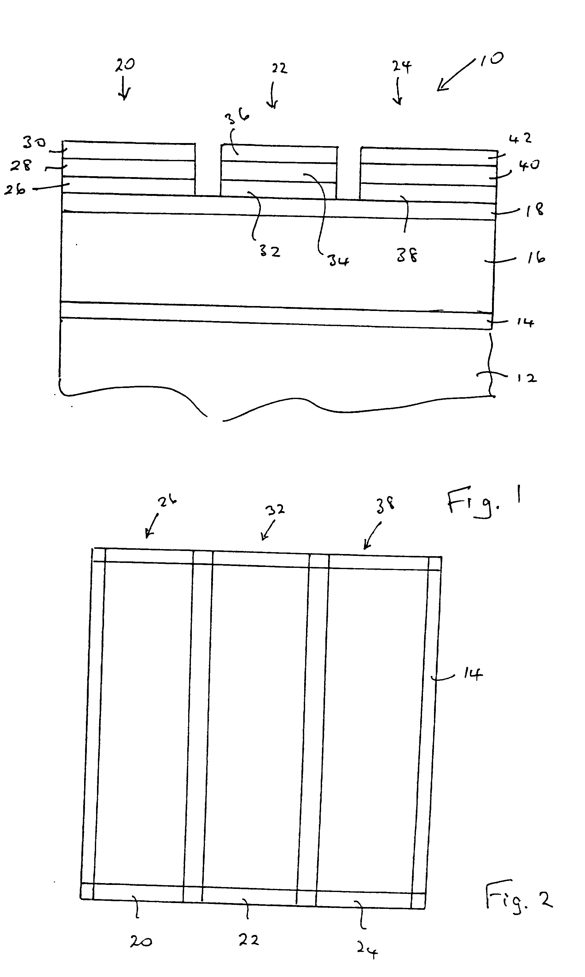
[0068] Several electroluminescent devices were constructed with magnesium calcium thioaluminate phosphor films. The magnesium content in the films corresponded to x=0.00, 0.10, 0.20, 0.35, 0.50, and 0.75 in the formula Mg.sub.xCa.sub.1-xAl.sub.2S.sub.4:Eu.

[0069] The substrate upon which each device was built consisted of alumina sheets measuring 5 centimeter by 5 centimeter, with a thickness of 0.1 centimeters. A gold patterned electrode was deposited on the alumina substrate, followed by a thick film dielectric structure, according to the methods described in U.S. patent application Ser. No. 09 / 540,288. A thin film dielectric consisting of barium titanate with a thickness of 100 to 200 nanometers was deposited on top of the thick film dielectric. The magnesium calcium thioaluminate phosphor film was deposited on top of the thin film dielectric film by electron beam evaporation using dual evaporation sources as described in U.S. patent application Ser. No. 09 / 747,315. The source mat...

example iv

[0074] Devices similar to those in Example III were constructed and tested. In all devices, the phosphor was formed from compositions of the formula Mg.sub.xCa.sub.1-xAl.sub.2S.sub.4:Eu with x=0.10. This composition closely corresponds to the single phase composition identified using x-ray diffraction measurements.

[0075] Phosphors were made with europium concentrations corresponding to 1.5 and to 3.5 atomic percent of the aluminum concentration. A control phosphor with no magnesium and 3.5 atomic percent europium was also prepared. In all cases the phosphor film was deposited at 200.degree. C.

[0076] The test results are shown in FIG. 8. The performance of all of the devices was quite similar, with the phosphor having magnesium and 1.5 atomic percent europium giving the highest luminance and the phosphor without magnesium giving the lowest luminance.


PUM

PropertyMeasurementUnit
thicknessaaaaaaaaaa
thicknessaaaaaaaaaa
temperatureaaaaaaaaaa

Abstract

A thin film phosphor for an electroluminescent device, and the electroluminescent device. The phosphor comprises a compound of the formula MgxCa1-xAl2S4:M, where the value of x is in the range 0<x<0.3 and M is a rare earth activator. Preferably, the value of x is in the range 0.05<x<0.20. A thin film phosphor for an electroluminescent device, the phosphor comprising magnesium calcium thioaluminate activated with a rare earth metal, the calcium thioaluminate containing an amount of magnesium to effect a lowering of the temperature of deposition of the phosphor on a substrate. A method for the preparation of the phosphor on a substrate, said method comprising the steps of: (i) depositing a mixtures of sulphides of magnesium, calcium, aluminum and rare earth metal on a substrate, and (ii) annealing the mixture of sulphides on the substrate so as to form the phosphor. The mixture of sulphides may be deposited on the substrate at a temperature of not greater than 200° C. Preferably, prior to step (i), a photoresist pattern is deposited on said substrate e.g. using photolithography.

Description

[0001] The present invention relates to single-phase magnesium calcium thioaluminate phosphors, particularly thin film magnesium calcium thioaluminate phosphors for electroluminescent displays and more particularly for electroluminescent displays employing thick film dielectric layers. The phosphor emits green light. The invention also relates to an electroluminescent apparatus employing such phosphors. The phosphors may be deposited at low temperatures and subsequently annealed to develop optimum phosphor performance. The deposition temperature is sufficiently low to prevent damage to photoresist materials that are required to be in place during the phosphor deposition process. The annealing step may be done following lithography steps required to define the phosphor pattern for the sub-pixels.[0002] In particular, the present invention relates to a high luminance green phosphor material for full colour electroluminescent displays that is compatible with photolithographic processes...

Claims


Application Information

Patent Timeline
Patent Type & Authority Applications(United States)
IPC IPC(8): C09K11/00C09K11/02C09K11/64C09K11/77C09K11/84H05B33/14
CPCC09K11/7706C09K11/7721Y10T428/26H05B33/14Y10S428/917C09K11/7734C09K11/77
Inventor CHEONG, DAN DAEWEONNAKUA, M. ABDULWU, XINGWEI
Owner IFIRE IP CORP
Why Eureka
Try Eureka