Liquid crystal device, mesomorphic functional material and liquid crystal apparatus

a liquid crystal device and functional material technology, applied in non-linear optics, instruments, transportation and packaging, etc., can solve the problems of power consumption, deterioration of fluorescent components, and lowering the recognizability of static images

Inactive Publication Date: 2003-02-27
CANON KK
View PDF0 Cites 27 Cited by
  • Summary
  • Abstract
  • Description
  • Claims
  • Application Information

AI Technical Summary

Benefits of technology

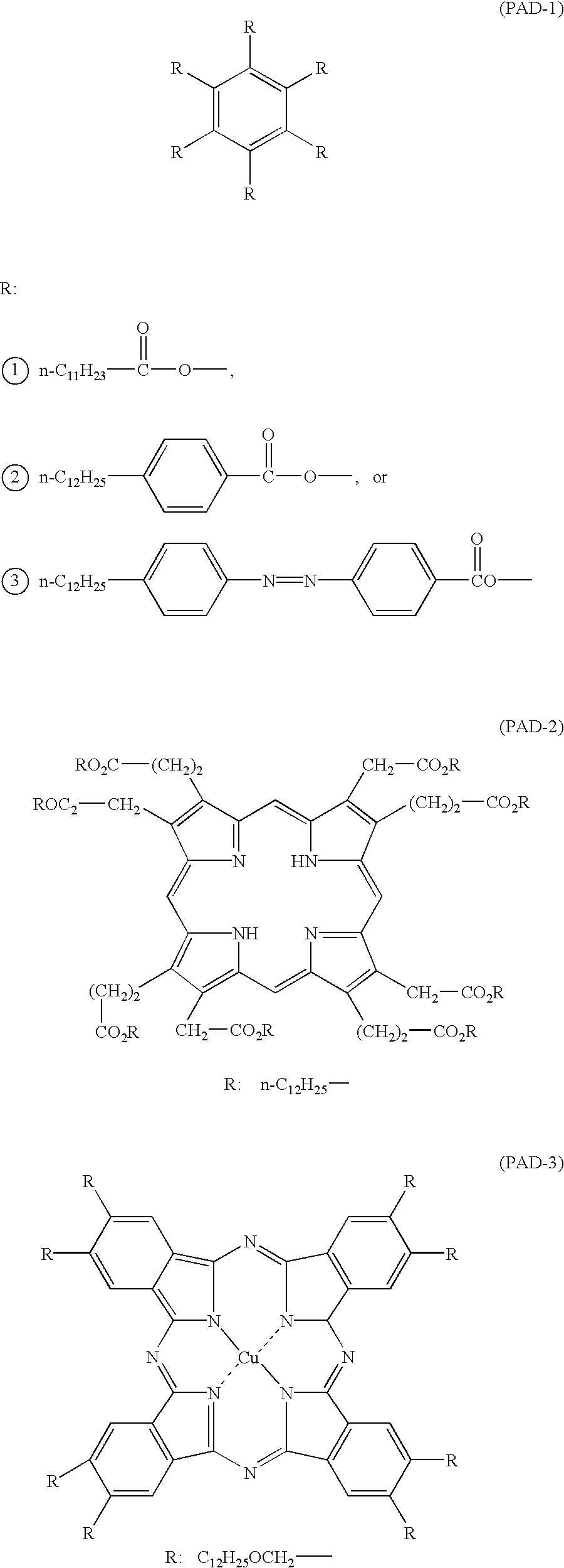
[0010] Another object of the present invention is to provide a mesomorphic functional material excellent in properties and suitable for a liquid crystal material of the liquid crystal device.
[0012] As a result of our study, we have found that it is possible to realize a liquid crystal device providing a high light-scattering state effectively utilizing a difference in refractive index characteristic between a discotic mesomorphic compound and a rod-shaped mesomorphic compound (as described later as to Table 1) by placing the mesomorphic compounds in such a state that the discotic mesomorphic compound and the rod-shaped mesomorphic compound essentially having mutually different molecular structures leading to different refractive index anisotropies are co-present in a phase separation state.

Problems solved by technology

Based on the operation characteristic, however, the CRT is accompanied with difficulties such that the recognizability of a static image is lowered due to flickering and scanning fringes caused by an insufficient resolution, and the fluorescent member is deteriorated due to burning or sticking.
Further, the CRT has generally consumed a larger electric power, thus being required to reduce its power consumption.
Further, the CRT structurally has a large rearward space behind the display surface to restrict facilitates for information equipment having the CRT, so that the space economization in offices at home may be obstructed thereby.
Further, a consumption power of liquid crystal display apparatus is largely occupied by the backlight.
However, the discotic mesomorphic compound and the rod-shaped mesomorphic compound have mutually similar chemical structures, thus providing an insufficient phase separation state.
As a result a light-scattering performance largely affected by the phase separation state is liable to become insufficient and a switching (optical response) ability of the rod-shaped mesomorphic compound is liable to be impaired.
Further, the reflectance is directly proportional to a cell thickness, so that a higher reflectance can lead to a smaller cell gap.
Thus, it is unnecessary to effect heat treatment or light irradiation at the time other than rewriting or display.
In the case of insufficient phase separation, isotropic liquid phase due to the discotic liquid crystal and the rod-shaped liquid crystal can still remain in the liquid crystal layer, thus lowering the light-scattering performance.

Method used


Image

  • Liquid crystal device, mesomorphic functional material and liquid crystal apparatus
  • Liquid crystal device, mesomorphic functional material and liquid crystal apparatus
  • Liquid crystal device, mesomorphic functional material and liquid crystal apparatus

Examples


example 2

[0206] The liquid crystal cell (device) using the blank cell B filled with the mesomorphic mixture (2) prepared in Example 1 was used as liquid crystal devices 303a, 303b and 303c for a projection optical system shown in FIG. 4.

[0207] When light from a light source 301 was projected onto a screen through the liquid crystal devices 303a, 303b and 303c under application of an electric field (5 V, 60 Hz) and under no electric field application.

[0208] As a result, a clear change in luminance on the screen was confirmed between the electric field application state and the state of no electric field application was confirmed.

example 3

[0209] An active liquid crystal device having an equivalent circuit as shown in FIG. 7 was prepared by using a single-crystalline silicon transistor 44 (on-resistance of 50 ohm), a liquid crystal cell (pixel size: 0.9 cm.sup.2) 70 using the blank cell B in combination with the mesomorphic mixture (2) (used in Example 1), and a ceramic capacitor 71 (2 nF).

[0210] When the thus-prepared liquid crystal device was supplied with a voltage signal (frame frequency 10 Hz) comprising a gate signal (selection period=30 psec) from a gate signal line 45 and a voltage signal (in sequence of 6 V, -6 V, 6 V, -6 V, 0 V, 0 V, 0 V and 0 V) from a data signal line 46, modulated light was observed through a polarizing microscope.

[0211] As described above, according to the present invention, it is possible to provide a polymer matrix-type liquid crystal device which does not require a polarizer and can be driven with a higher brightness (luminance) and at a lower power consumption compared with the conve...

second embodiment

[0212] (For Second Embodiment)

EXAMPLE 4

[0213] A mesomorphic mixture (3) was prepared by mixing a polymerizable discotic mesomorphic compound A shown below with a rod-shaped mesomorphic compound B shown below in a weight ratio A / B=50 / 50, and a mesomorphic mixture (4) was prepared by mixing the polymerizable discotic mesomorphic compound A with the rod-shaped mesomorphic compound B in a weight ratio A / B=25 / 75. The respective compounds (or composition) were mixed in an isotropic liquid state.

[0214] 16

[0215] R.sub.1 or R.sub.2

[0216] R.sub.1: --OCOPhO(CH.sub.2).sub.7CH.sub.3

[0217] R.sub.2: --OCOPhO(CH.sub.2).sub.11--OCOCH.dbd.CH.sub.2 17

[0218] The mesomorphic compound A was a mixture of a1(R.sub.1 / R.sub.2=5 / 1 by mol), a2(R.sub.1 / R.sub.2=4 / 2) and a3(R.sub.1 / R.sub.2=3 / 3) in a weight ratio (a1:a2:a3)=22:59:16.

[0219] Phase Transition Temperature (.degree. C.) 18

[0220] Dr: discotic rectangular phase,

[0221] Nd: nematic discotic phase.

[0222] 19

[0223] Phase Transition Temperature (.degree. C.)...


PUM

PropertyMeasurementUnit
domain sizeaaaaaaaaaa
wt. %aaaaaaaaaa
thicknessaaaaaaaaaa

Abstract

A liquid crystal device has a liquid crystal layer of a liquid crystal composition comprising a discotic mesomorphic compound and a rod-shaped mesomorphic compound. The discotic mesomorphic compound and the rod-shaped mesomorphic compound are essentially mutually different in molecular structure and refractive index anisotropy and are co-present in the liquid crystal layer in a mutual phase separation state, thus improving a light-scattering performance of the liquid crystal device.

Description

FIELD OF THE INVENTION AND RELATED ART[0001] The present invention relates to a liquid crystal device for use in light-valves for flat panel displays, paper displays, projection displays, printers, etc. The present invention also relates to a mesomorphic functional material suitable for constituting the liquid crystal device and a liquid crystal apparatus including the liquid crystal device.[0002] The most popular and extensively used display may be CRTs (cathode ray tubes) which have been heretofore used for displaying motion pictures of television and video tape recorders or as monitor displays for personal computers. Based on the operation characteristic, however, the CRT is accompanied with difficulties such that the recognizability of a static image is lowered due to flickering and scanning fringes caused by an insufficient resolution, and the fluorescent member is deteriorated due to burning or sticking. Further, the CRT has generally consumed a larger electric power, thus bei...

Claims


Application Information

Patent Timeline
Patent Type & Authority Applications(United States)
IPC IPC(8): C09K19/32C09K19/38G02F1/1333G02F1/1334G02F1/137
CPCB32B17/10036B32B17/10174C09K19/32C09K19/3861Y10T428/10G02F1/1334G02F2001/13756Y10T428/1036G02F1/133365C09K2323/03C09K2323/00G02F1/13756
Inventor SATO, KOICHINAKAMURA, SHINICHINOGUCHI, KOJI
Owner CANON KK
Why Eureka
Try Eureka