Electro-mechanical scanned array system and method

a scanning array and electromechanical technology, applied in the field of antenna systems, can solve the problems of inability to employ multi-frequency or relatively broadband systems such as dual-band cellular base station antennas, unacceptably high current cost of phased array technology for most applications, etc., and achieve the effect of improving signal quality indication

Inactive Publication Date: 2003-03-06
E TENNA CORP
View PDF0 Cites 153 Cited by
  • Summary
  • Abstract
  • Description
  • Claims
  • Application Information

AI Technical Summary

Benefits of technology

0017] In yet another embodiment, the present invention provides a method for a radio including a phased array antenna system. The method includes steering an antenna beam to a remote radio target with a planar fractal beamformer, detecting a signal quality indication associated with radio communication with the remote radio target, and applying corrected control signals to time delay elements of the planar fractal beamformer to steer the antenna beam to improve the signal quality indication.

Problems solved by technology

Existing phased array technology is unacceptably expensive for most of these applications.
Existing technology is also narrow-band, and thus cannot be employed in multi-frequency or relatively broadband systems such as dual-band cellular base station antennas.
Such conventional phase shifters are thus relatively bulky and expensive.
Phase shifters are also generally radio frequency (RF)-active devices that require a comparatively large amount of power and may interfere with the transmitted signal.
Another disadvantage is that, because the phase shifter alters the phase of an input signal thereby only simulating a time delay, a fixed, progressive time delay between elements is obtained only over a relatively narrow band of frequencies.

Method used


Image

  • Electro-mechanical scanned array system and method
  • Electro-mechanical scanned array system and method
  • Electro-mechanical scanned array system and method

Examples


first embodiment

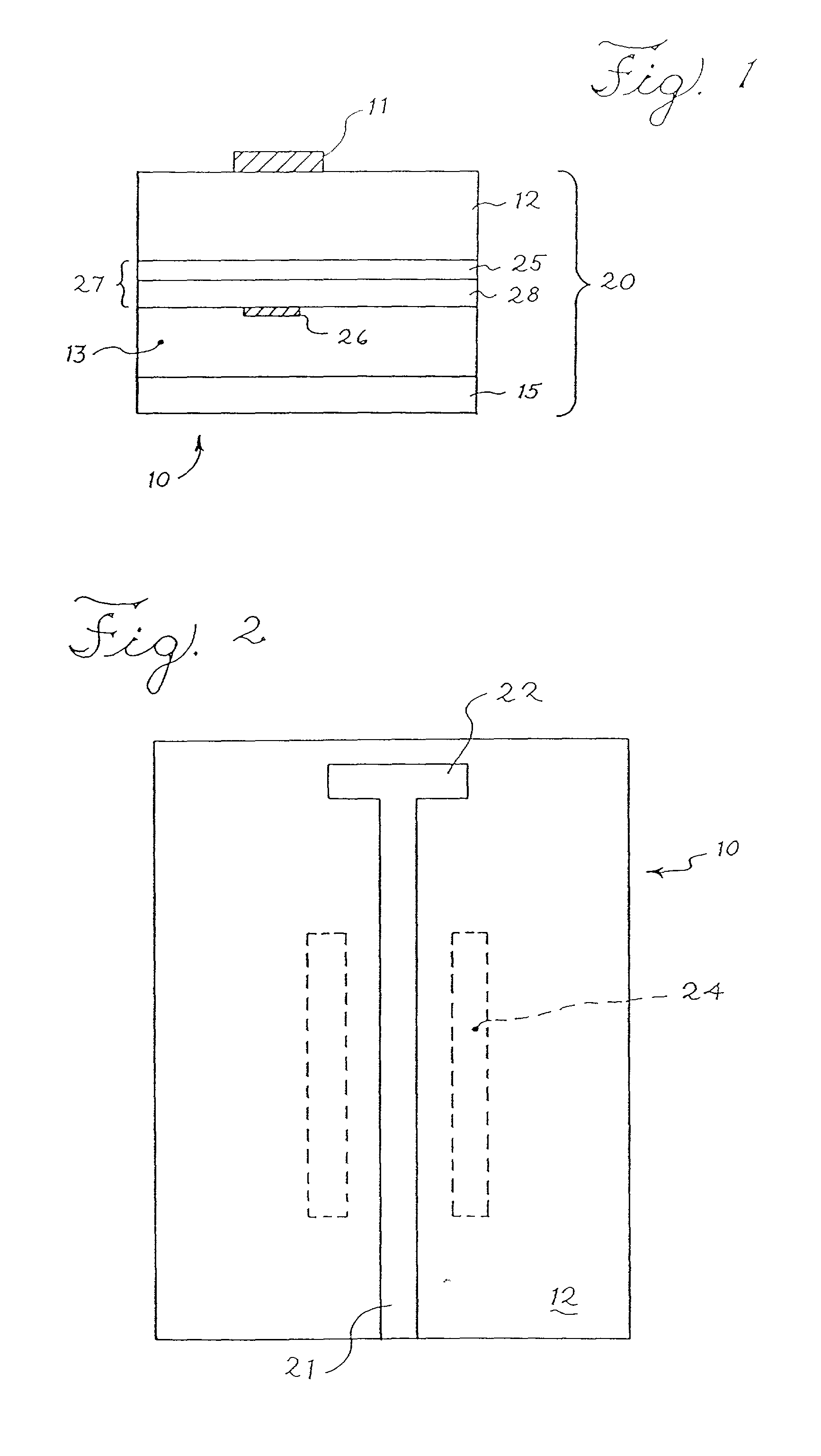
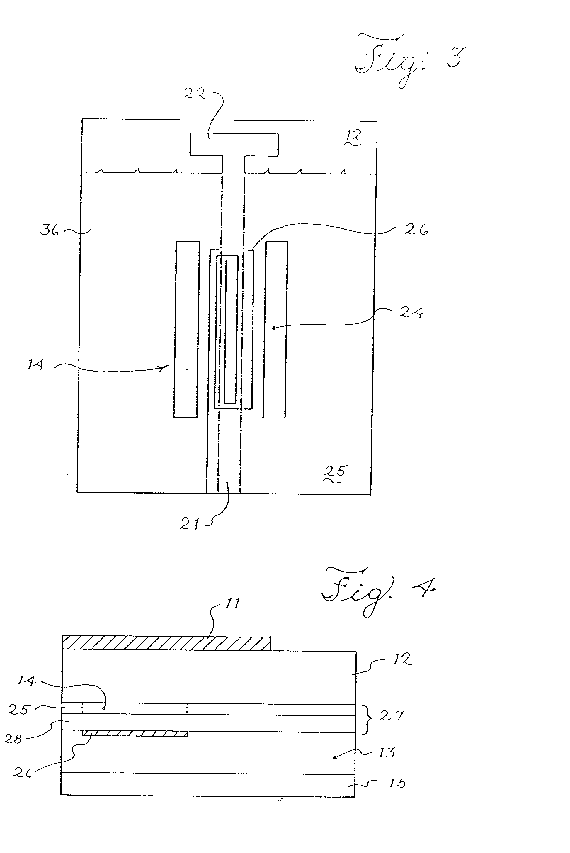
[0057] The microwave transmission line 11 may contain a microstrip feedline 21 and a patch antenna 22. The microwave transmission line 11 thus forms a transmission line waveguide means for guiding an electromagnetic signal in three dimensions. The microwave transmission line 11 may be constructed from a conductor, such as copper, aluminum, silver, or a comparable alloy, to allow electromagnetic signals to propagate along the microstrip feedline 21 and optionally be transmitted by or received by the patch antenna 22. Although the device may be a broadband device, the wavelength of the signals transmitted along the microstrip feedline 21 may be optimized generally for a particular frequency range, such as either microwave signals or millimeter wave signals, e.g. say the Ka band (27-40 GHz range) or X band (10 GHz range). The microstrip feedline 21 and the patch antenna 22 in the first embodiment may be disposed on the same composite substrate 20, although it is not necessary for micro...

second embodiment

[0143] FIG. 26 is an antenna system 2600. The antenna system 2600 includes radiating elements 2602, a beamformer 2604 and a controller 2606. The antenna system 2600 further includes a radio frequency to intermediate frequency (RF to IF) section 2608.

[0144] The radiating elements 2602 in the embodiment of FIG. 26 are dual-band patch antennas. Other radiating elements may be used instead. The beamformer 2604 comprises a fractal corporate power divider with variable true time delay and may be embodied as shown to the left in FIG. 26. The beamformer 2604 includes a feed port 2610 and output ports 2612 coupled with the dual-band patch antennas or radiating elements 2602.

[0145] The RF to IF circuit 2608 includes a diplexer 2620, a low noise amplifier 2622, a down-converter 2624, a diplexer 2626, an up-converter 2628 and a power amplifier (PA) 2630. The RF to IF circuit 2608 receives an intermediate frequency signal at an IF port 2632. The intermediate frequency signal is provided to the u...

third embodiment

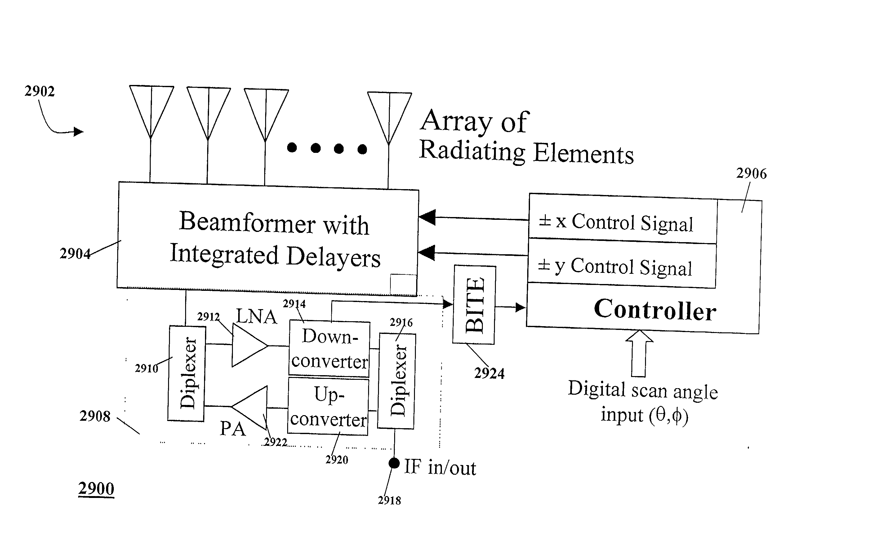
[0157] FIG. 29 is a block diagram of an antenna system 2900. The antenna system 2900 includes an array of radiating elements 2902, a beamformer 2904 and a controller 2906. The antenna system 2900 in the embodiment of FIG. 29 further includes a radio frequency to intermediate frequency circuit 2908 and build-in test equipment 2924. The RF to IF circuit 2908 includes a diplexer, a low-noise amplifier (LNA) 2912, a down-converter 2914, a diplexer 2916, an up-converter 2920 and a power amplifier (PA) 2922.

[0158] The beamformer 2904 has a feed port 2930 and preferably includes a two-dimensional arrangement of output ports. The radiating antenna elements 2902 are coupled with output ports of the beamformer 2904. The antenna control unit 2906 is coupled with the beamformer 2906 to steer a beam of the antenna system 2900. The diplexer 2910 of the RF to IF circuit 2908 is coupled with the feed port 2930 of the beamformer 2904. For reception, radio frequency (RF) signals from the feed port 29...


PUM


Abstract

An antenna system includes a beamformer having a feed port and a one-dimensional or two-dimensional arrangement of output ports, radiating antenna elements coupled with output ports of the beamformer, and an antenna control unit coupled with the beamformer to steer a beam of the antenna system. The antenna system forms an electrically steerable, phased array antenna having a beam steering angle which is constant over a very broad band of frequencies. Specific applications for the antenna system include satellite communications including tracking low earth orbiting satellites, radar systems and data links using a steerable antenna for self-installation, self-healing and adaptation.

Description

[0001] This application is related to application Ser. No. 09 / 839,323 entitled "Variable Time-Delay Microwave Transmission Line," filed Apr. 20, 2001 in the name of James D. Lilly, and application Ser. No. 09 / 863,975 entitled "Planar, Fractal, Time-Delay Beamformer," filed May 23, 2001 in the names of William E. McKinzie, III and James D. Lilly, both of which are commonly assigned to the assignee of the present application and incorporated in their entirety herein by this reference.[0002] This application relates generally to phased arrays. More particularly, this application relates to electro-mechanical scanned array systems and methods.[0003] Phased arrays are electronic devices used in forming antenna systems. A phased array antenna includes an array of antenna elements which produces one or more steerable beams of radio frequency energy. The relative amplitude and phase shift across the array of antenna elements defines the antenna beam. This relative amplitude and phase state ...

Claims


Application Information

Patent Timeline
Patent Type & Authority Applications(United States)
IPC IPC(8): H01Q3/22H01Q3/26H01Q21/00
CPCH01Q3/22H01Q3/2605H01Q3/2682H01Q21/0006H01P1/184
Inventor LILLY, JAMES D.MCKINZIE, WILLIAM E. III
Owner E TENNA CORP
Why Eureka
Try Eureka