Eureka AIR delivers breakthrough ideas for toughest innovation challenges, trusted by R&D personnel around the world.

Liquid and low melting coatings for stents

a coating and liquid technology, applied in the field of coating stents, can solve the problems of stents located within the lumen of the body not always preventing partial or complete restenosis, both types of coatings are susceptible to breaking and cracking, etc., and achieves enhanced adhesion of coatings, low boiling point, and easy removal

Inactive Publication Date: 2003-05-01
COVIDIEN LP +1
View PDF99 Cites 126 Cited by
  • Summary
  • Abstract
  • Description
  • Claims
  • Application Information

AI Technical Summary

Benefits of technology

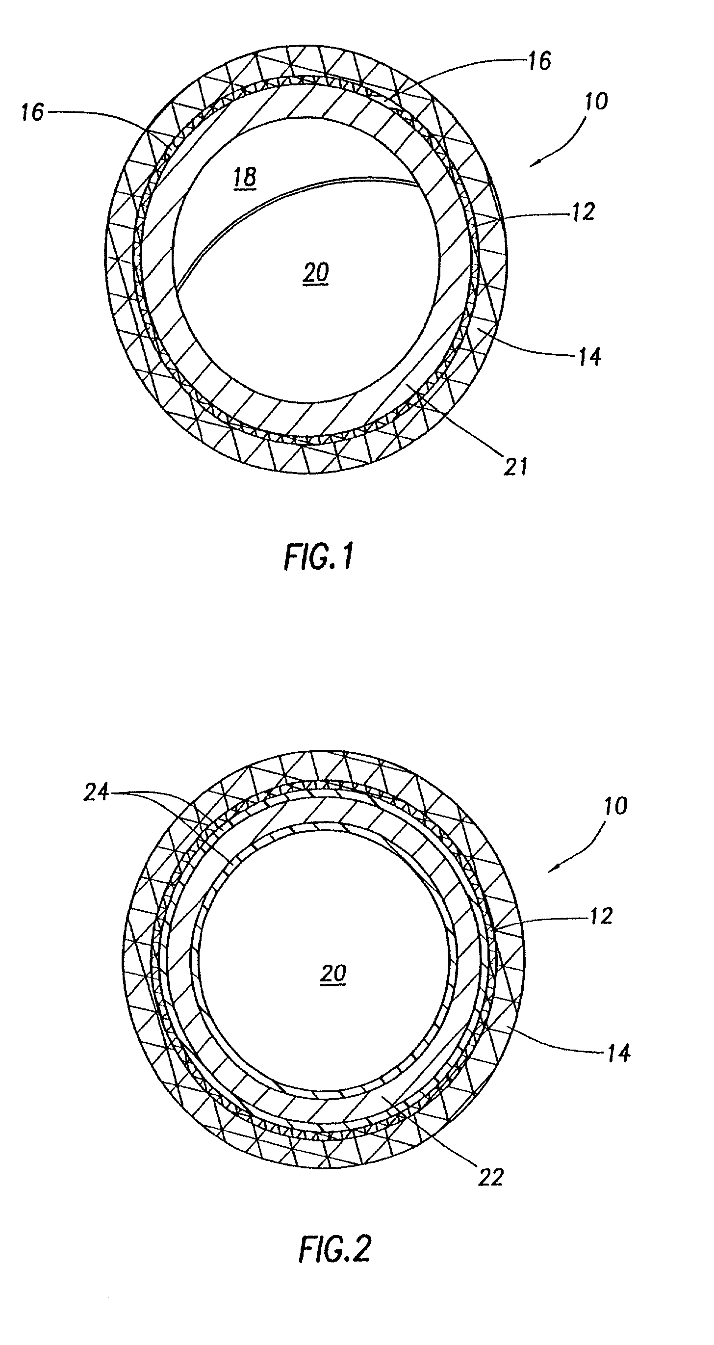
[0030] An artery 10 containing a coated stent 22 prepared according to an embodiment herein is shown in FIG. 2. The stent has a coating 24 containing a carrier and a bioactive compound which inhibits restenosis. By using a stent having this coating 24, the tears 16 shown in FIG. 1 in the endothelium 12 may be reduced or eliminated. Additionally, the mass 18 created by hyperproliferation of smooth muscle cells 14, as shown in FIG. 1, is eliminated or substantially reduced.
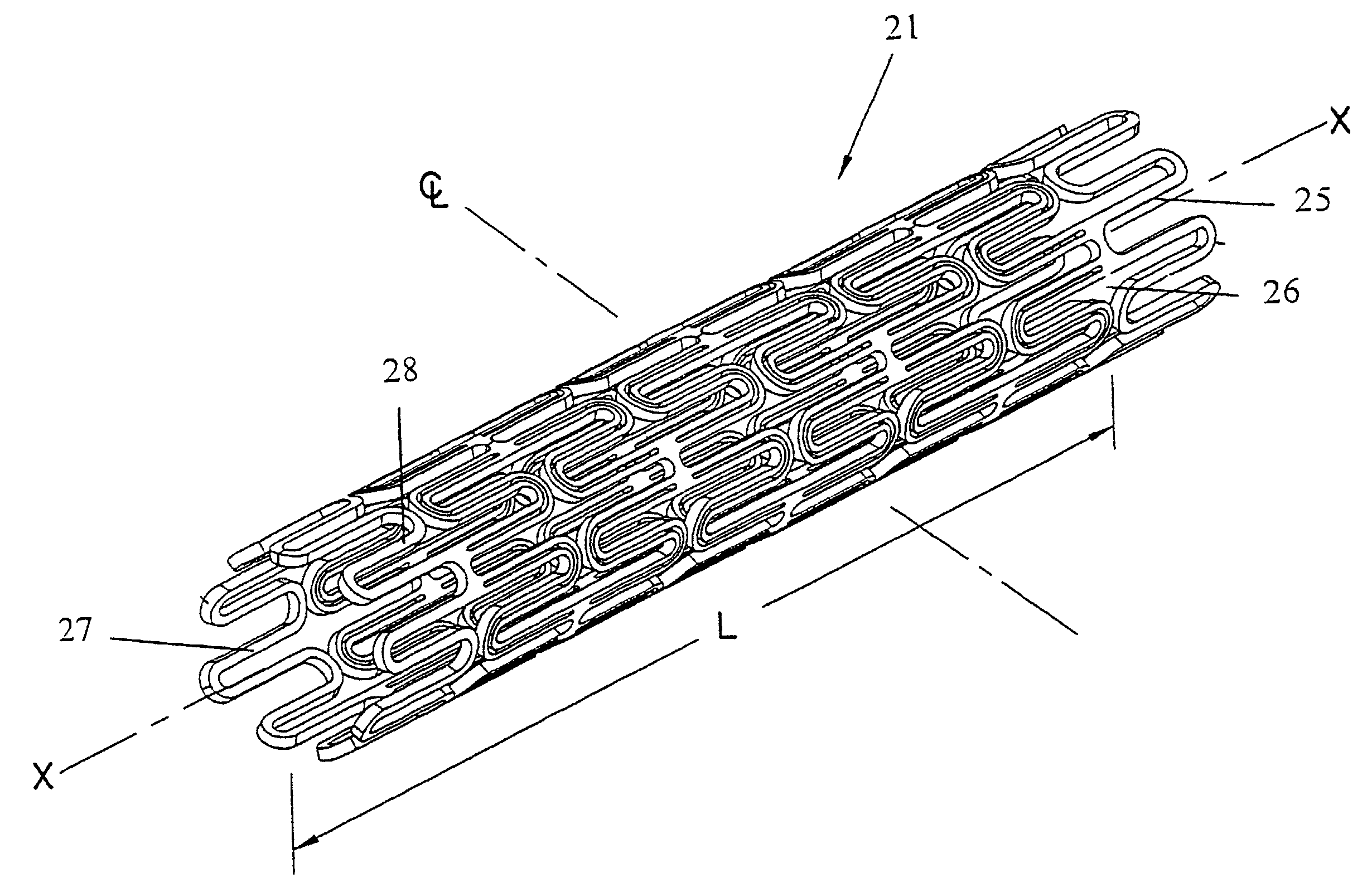
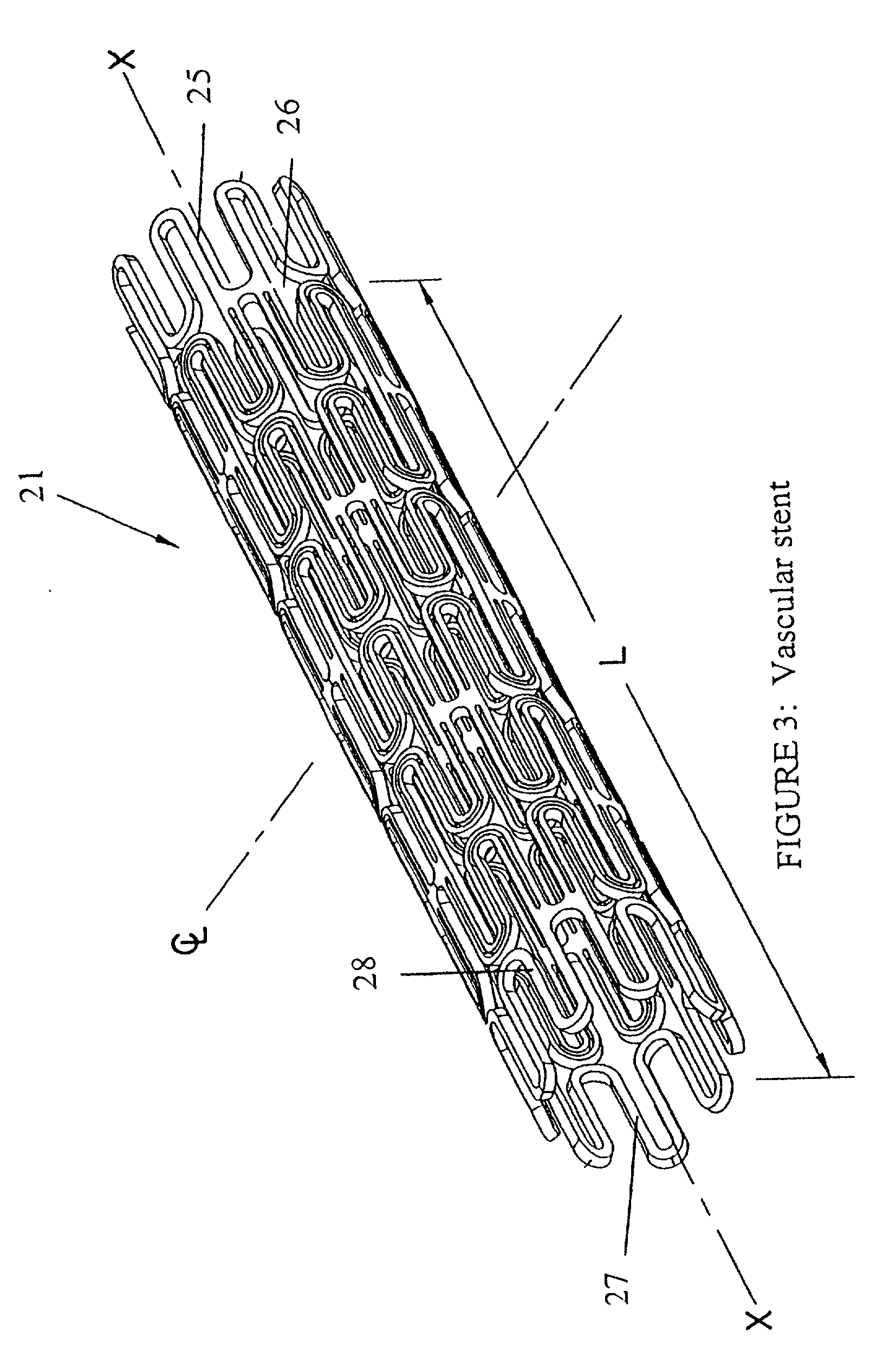
[0082] In accordance with methods and compositions described herein, restenosis may be prevented or lessened using localized delivery of HMG-CoA reductase inhibitors from a liquid or low-melting carrier coupled to a stent placed in a body lumen. Preferably, metal stents are coated with a biocompatible coating composition comprising a carrier and an effective amount of an HMG-CoA reductase inhibitor. The coated stent can be deployed during any conventional percutaneous transluminal coronary angioplasty (PTCA) procedure. Controlled delivery from a stent of the active HMG-CoA reductase inhibitor, using a coating such as that described herein, in an effective amount, can inhibit the regrowth of plaque and prevent restenosis. While the stents shown and described in the various embodiments are vascular stents, any type of stent suitable for deployment in a body lumen of a patient may be used with the coatings described herein.

Problems solved by technology

However, there is a risk that the artery may re-close within a period of from one day to approximately six months after the procedure.
A problem with known biodegradable and biostable stent coatings is that both types of coatings are susceptible to breaking and cracking during the temperature changes and expansion / contraction cycles experienced during stent fabrication and use.
Stents located within a lumen in the body may not always prevent partial or complete restenosis.
In particular, stents do not always prevent the re-narrowing of an artery following PTCA.
However, delivering drugs in this manner may result in undesirable side effects in other areas of the body unrelated to the vascular occlusion.
Also a drug which is delivered systemically is less effective in achieving the desired effect in the local area of the body in which it is actually needed.
For example, an anti-restenosis drug delivered systemically may be sequestered or metabolized by other parts of the body, resulting in only a small amount of the drug reaching the local area where it is needed.
One problem with the biodegradable carriers currently proposed for incorporation in coatings for stents and angioplasty balloons is that, because they are invariably solids at body temperature and below, they may degrade into fragments which can be sharp.
These fragments can damage the endothelium, and thus contribute to restenosis.

Method used


Image

  • Liquid and low melting coatings for stents
  • Liquid and low melting coatings for stents
  • Liquid and low melting coatings for stents

Examples


example 1

[0086] 100 mg EVA (ethylene-vinyl acetate) polymer and 10 mg of cerivastatin were dissolved in 10 ml methylene chloride solution at room temperature. The solution was poured onto a glass plate and the solvent was allowed to evaporate for 12-24 hours. After almost complete removal of the solvent, the cerivastatin-loaded EVA film was removed from the glass plate and was cut to 1.5 cm by 1.5 cm size. The film was mounted on a Palmaz-Schatz coronary endovascular stent. Control EVA films were prepared in the following manner: 100 mg EVA polymer was dissolved in 10 ml methylene cloride solution at room temperature. The solution was poured onto a glass plate and the solvent was allowed to evaporate for 12-24 hours. After almost complete removal of the solvent, the control EVA film was removed from the glass plate and was cut to 1.5 cm by 1.5 cm size. The control film was mounted on a Palmaz-Schatz coronary endovascular stent. Release profiles were obtained for the coated stents.

example 2

[0087] A 10% w / w solution of cerivastatin in vitamin E was created by the following method. Four (4) mg of cerivastatin was dissolved in one hundred (100) .mu.l of methylene chloride. This solution was added to 36 mg of liquid vitamin E and mixed manually by stirring. The solution was allowed to stand at room temperature for one hour to enable the methylene chloride to evaporate from the solution. The resulting cerivastatin / vitamin E mixture was used to coat three "Protge" stents by simple surface application. Approximately 10-12 mg of vitamin E and drug was deposited on each stent.

example 3

[0088] A coated stent prepared according to Examples 1 and 2 is immersed in an Eppendorf tube containing 1 ml phosphate buffered saline (PBS) and incubated on a rotator in a 37.degree. C. oven. Buffer exchanges are performed at 1, 2, and 4 days following immersion in PBS. Collected samples are assayed for rifampin concentration using a UV-VIS spectrophotometer.


PUM

PropertyMeasurementUnit
melting pointaaaaaaaaaa
viscosityaaaaaaaaaa

Abstract

A method for forming liquid coatings for medical devices such as stents and angioplasty balloons is provided. The liquid coatings can be made from biodegradable materials in liquid, low melting solid, or wax forms, which preferably degrade in the body without producing potentially harmful fragments. The liquid coatings may also contain biologically active components, which are released from the coatings through diffusion from the coatings and the degradation of the coatings.

Description

[0001] This application is a continuation-in-part of co-pending U.S. patent application Ser. No. 09 / 991,235, filed Nov. 22, 2001, entitled "Stent Coatings Containing HMG-CoA Reductase Inhibitors," which is hereby incorporated herein by reference in its entirety.[0002] 1. Field of the Invention[0003] The present invention generally relates to coated stents, compositions for coating stents, methods of making coated stents, and methods of using coated stents.[0004] 2. Description of the Related Art[0005] Stents are often used in the treatment of atherosclerosis, a disease of the vascular system in which arteries become partially, and sometimes completely, occluded with substances that may include lipids, cholesterol, calcium, and various types of cells, such as smooth muscle cells and platelets. Atherosclerosis is a very common disease which can be fatal, and methods of preventing the accumulation of occluding compounds in arteries are being investigated.[0006] Percutaneous translumina...

Claims


Application Information

Patent Timeline
Patent Type & Authority Applications(United States)
IPC IPC(8): A61L31/16
CPCA61F2/91A61F2250/0067A61L31/08A61L31/16A61L2300/416A61F2230/0013A61L2300/606A61L2/16A61L2/28A61F2/82A61L2300/434A61L31/048A61L31/049A61L31/06A61L31/10A61L31/125A61L2300/602A61L2300/802A61L2420/04
Inventor PATHAK, CHANDRASHEKHAR
Owner COVIDIEN LP
Why Eureka
Eureka Blog
Learn More