High polymer electrolyte fuel cell and electrolyte film-gasket assembly for the fuel cell
- Summary
- Abstract
- Description
- Claims
- Application Information
AI Technical Summary
Benefits of technology
Problems solved by technology
Method used
Image

Examples
embodiment 4
[0120] Embodiment 4
[0121] FIGS. 25 through 28 illustrate an MEA of this embodiment. Like Embodiment 1, a gasket 120 is integrally joined to the peripheral portion of an electrolyte membrane 110 by injection molding. The gasket 120 has gas flow channels 126a and 126b for connecting a gas flow channel 116 formed in the front surface of an anode 115 joined to the electrolyte membrane 110 to fuel gas inlet-side manifold aperture 121a and outlet-side manifold aperture 121b, respectively.
[0122] Furthermore, the gasket 120 has gas flow channels 128a and 128b for connecting a gas flow channel 118 formed in the front surface of a cathode 117 joined to the electrolyte membrane 110 to manifold apertures 122a and 122b, respectively. For the separator plate to be combined with this MEA, a metal plate in the form of a flat plate used in Embodiment 2 is used.
embodiment 5
[0123] Embodiment 5
[0124] FIG. 29 shows a separator plate of this embodiment, and FIGS. 30 and 31 illustrate a cell structure composed of a combination of this separator plate and an MEA.
[0125] A separator plate 130 is made of a metal plate, and a portion 134 forming a gas flow channel is molded in a corrugated or wavy form by press working. The separator plate 130 has an inlet-side manifold aperture 131a and an outlet-side manifold aperture 131b for the fuel gas, and an inlet-side manifold aperture 132a and an outlet-side manifold aperture 133b for the oxidant gas.
[0126] An anode 145 and a cathode 147 are joined to the exposed surfaces of the electrolyte membrane 110 having a gasket 140 integrally joined to the peripheral portion thereof by injection molding. This MEA and the separator plate 130 are alternately stacked to assemble a cell. Then, a fuel gas flow channel is formed between the anode 145 and the separator plate 130 by a recessed portion 135 of the corrugated section 134...
embodiment 6
[0130] Embodiment 6
[0131] FIG. 32 shows an MEA according to this embodiment. Referring to FIGS. 33 through 37, the following description will explain a method for manufacturing this MEA.
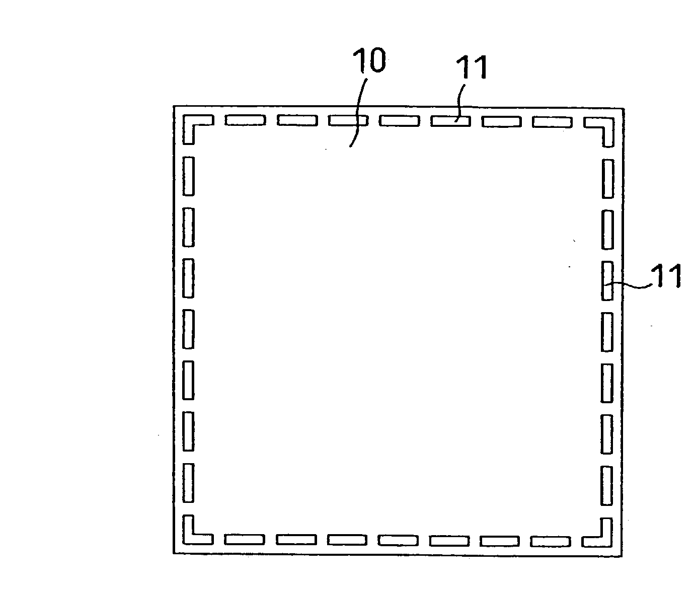
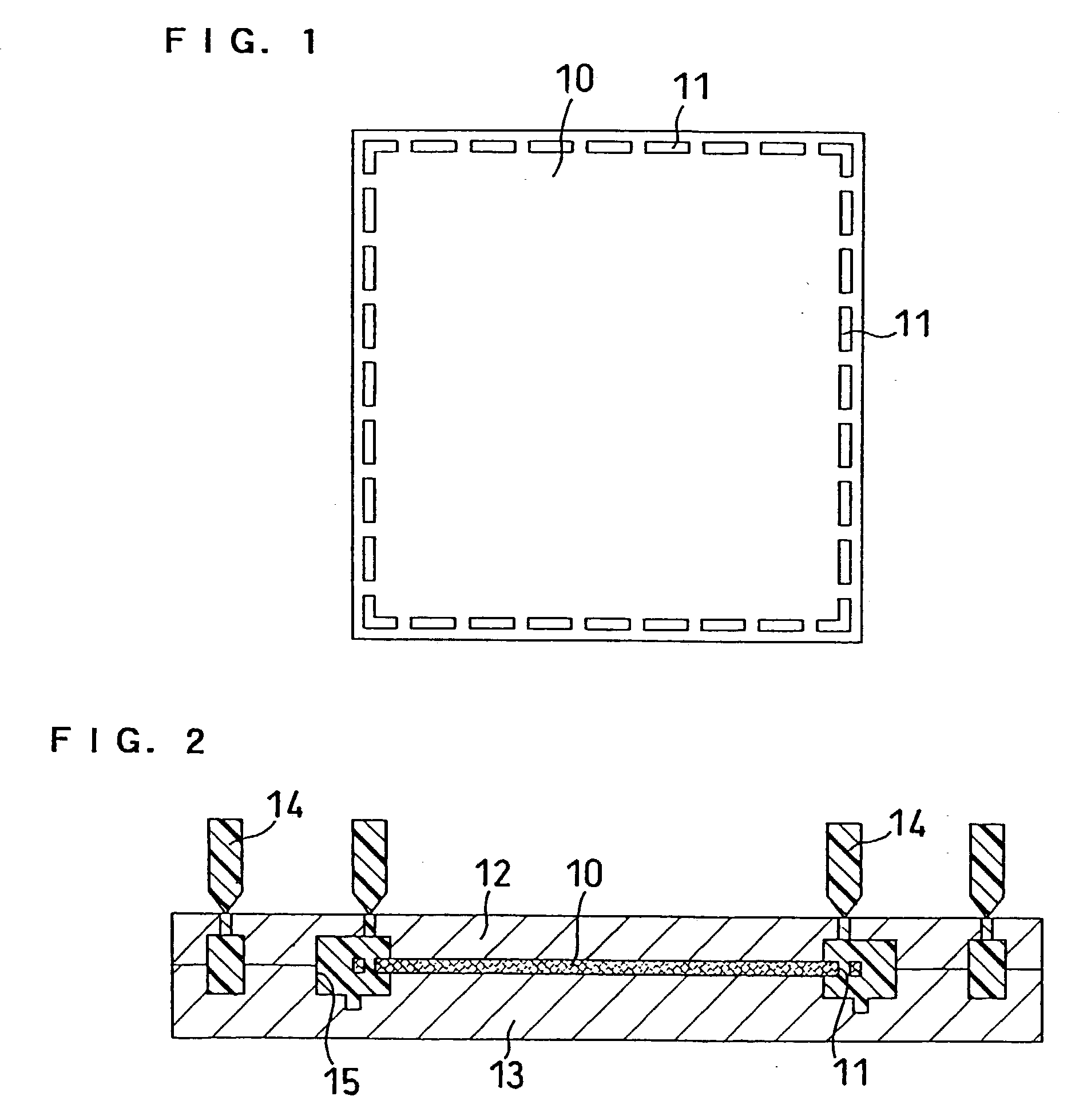
[0132] First, as shown in FIG. 35(a), catalyst layers 214 are formed, respectively, on both the front and rear surfaces of a polymer electrolyte membrane 210, except for the peripheral portion thereof. One of the catalyst layers is an anode-side catalyst layer, while the other is a cathode-side catalyst layer. It is possible to change the compositions of both the catalyst layers if necessary. Next, as illustrated in FIG. 35(b), protective films 212 are superimposed to cover the catalyst layers 214 and the entire exposed surfaces of the electrolyte membrane. Subsequently, the resultant laminated product is punched out, thereby to cut into a predetermined size and form a plurality of through-holes 211 in the peripheral portion thereof. Consequently, as illustrated in FIG. 35(c), an assembly comprising ...
PUM
| Property | Measurement | Unit |
|---|---|---|
| Pressure | aaaaa | aaaaa |
| Pressure | aaaaa | aaaaa |
| Pressure | aaaaa | aaaaa |
Abstract
Description
Claims
Application Information