Filtration system and method for obtaining a cytology layer

a cytology and filter system technology, applied in the field of specimen vials, can solve the problems of insufficient consistency, reliability, speed and automation of automated equipment developed for processing liquid-based specimens, and add time, material and labor costs to the processing required, so as to meet current and projected needs in cancer screening and other cytology-based medical, analytical, screening and diagnostic procedures. , the effect of simple and inexpensive releasable coupling and avoiding contamination

a cytology and filter system technology, applied in the field of specimen vials, can solve the problems of insufficient consistency, reliability, speed and automation of automated equipment developed for processing liquid-based specimens, and add time, material and labor costs to the processing required, so as to meet current and projected needs in cancer screening and other cytology-based medical, analytical, screening and diagnostic procedures. , the effect of simple and inexpensive releasable coupling and avoiding contamination

US20030092170A1Inactive Publication Date: 2003-05-15HOLOGIC INC

Image

  • Filtration system and method for obtaining a cytology layer
  • Filtration system and method for obtaining a cytology layer
  • Filtration system and method for obtaining a cytology layer

Examples


Embodiment Construction

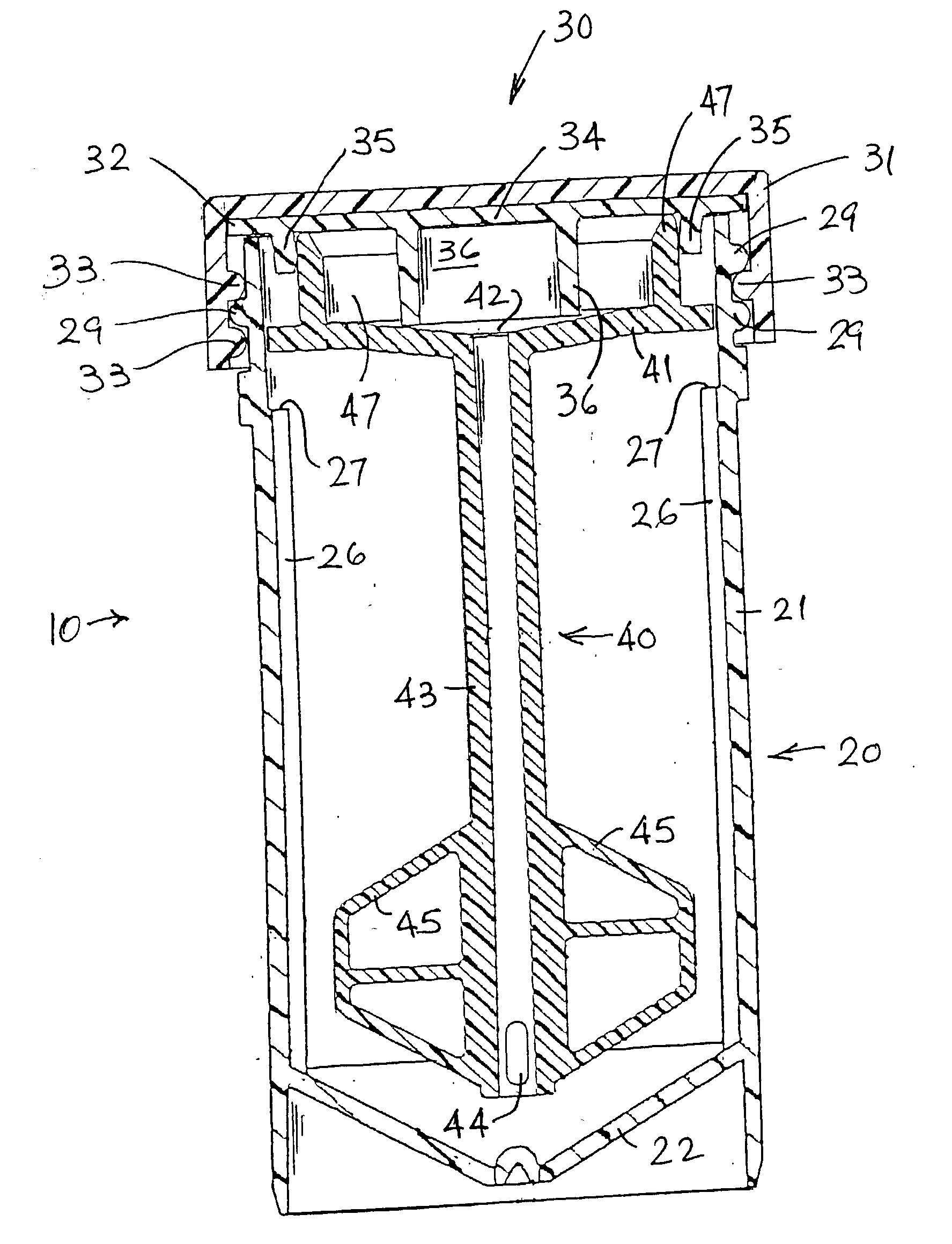
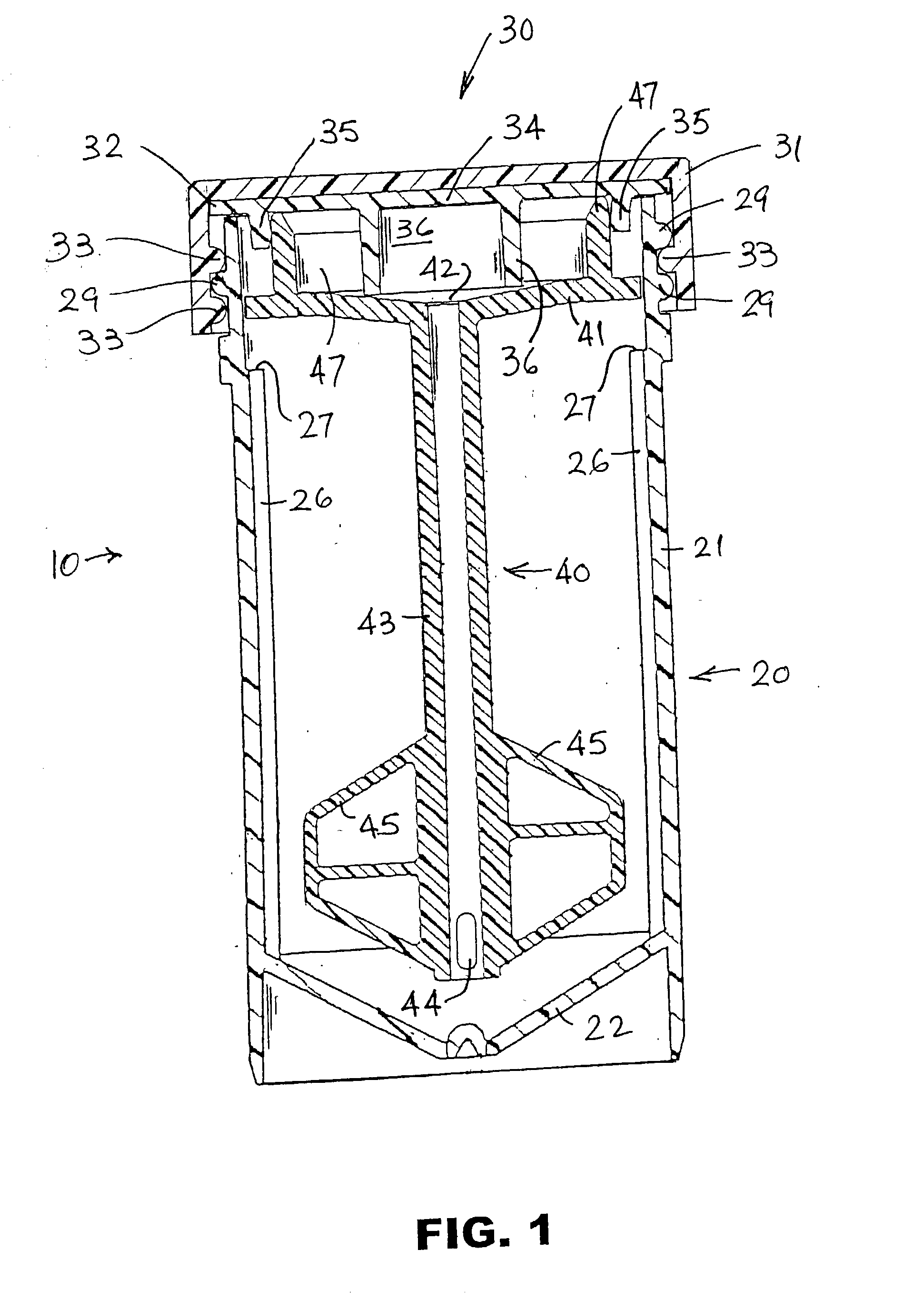
[0095] A full description of this vial-based specimen handling and processing system must begin with the vial itself, which consists of a container, a cover and a processing assembly (stirrer) in the vial.

[0096] Specimen Vial

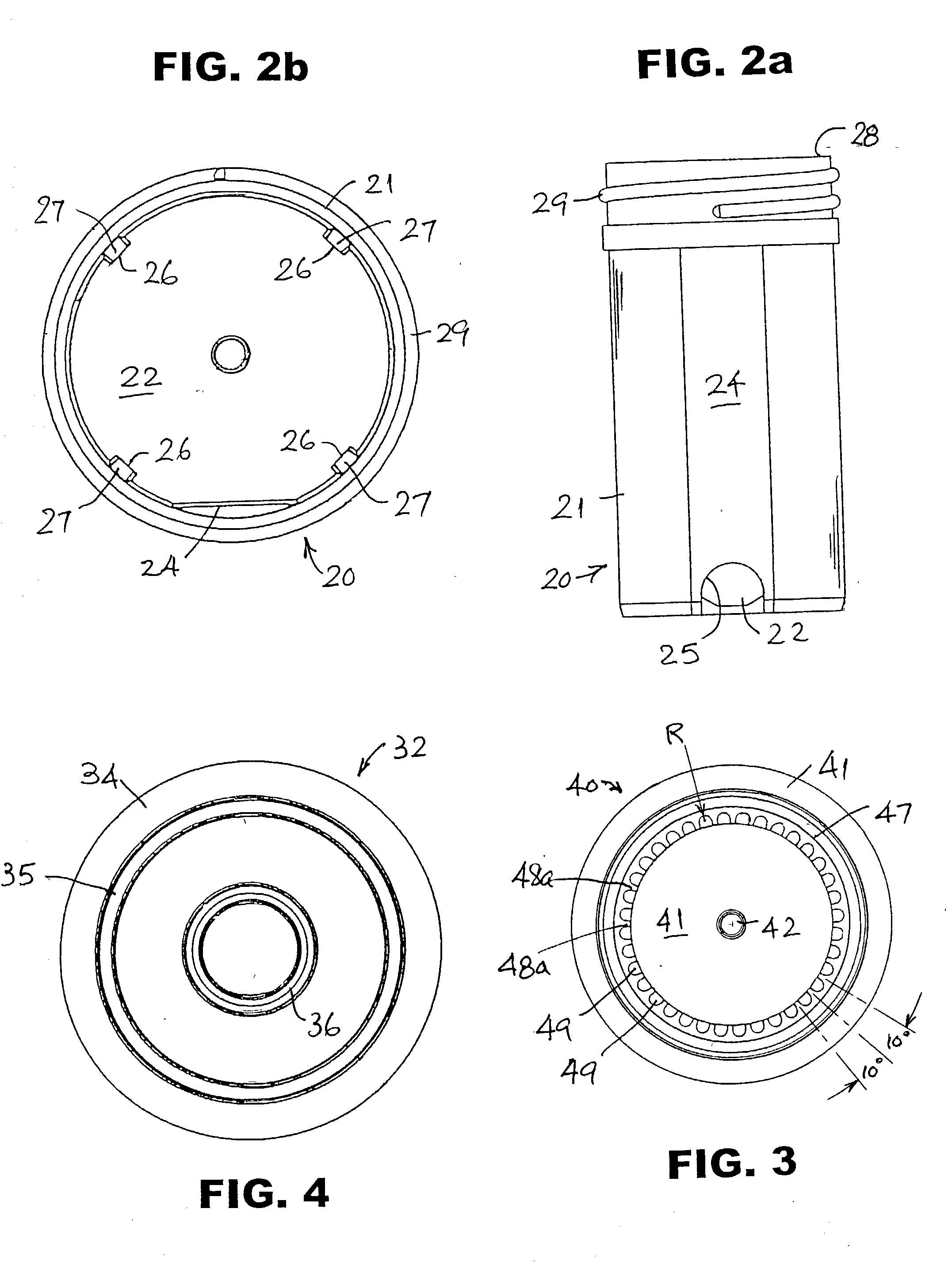
[0097] Referring to FIGS. 1, 2a and 2b, the vial 10 comprises a container 20, a cover 30 and a processing assembly 40. Processing assembly 40 is designed to carry out several functions, among them mixing, and for this preferred rotary embodiment will be referred to as a stirrer for the sake of convenience. Container 20 preferably is molded of a translucent plastic, preferably polypropylene, and has a substantially cylindrical wall 21, surrounding its longitudinal axis, joined to a conical bottom wall 22. Possible alternative plastics include ABS and polycyclohexylenedimethylene terephthalate, glycol (commercially available from Eastman Kodak Co. under the name EASTAR.RTM. DN004). A small portion 24 of wall 21 preferably is flat, the outer surface of the flat por...


PUM

PropertyMeasurementUnit
angleaaaaaaaaaa
heightaaaaaaaaaa
inner diameteraaaaaaaaaa

Abstract

A filter assembly for separating and collecting a layer of particulate matter (e.g., cells) from a liquid containing the particulate matter (e.g., a biological fluid specimen). The filter assembly has a holder and contiguous inner and outer fluid pervious media. The outer fluid pervious medium is attached to the sidewall of the holder. The inner fluid pervious medium is of low fluidic impedance relative to the outer fluid pervious medium. The filter assembly is designed for use in a separation housing that defines two flow paths between inlet and outlet, one directly through the filter and the other around the periphery of the filter. The inlet portion of the housing has a central inlet in a radially sloped surface that faces the filter collection site. A movable suction head is adapted to cooperate with the housing and the filter assembly.

Description

[0001] This application claims the benefit of commonly owned U.S. provisional application Nos. 60 / 330,092, filed Oct. 19, 2001, 60 / 372,080, filed Apr. 15, 2002, and 60 / 373,658, filed Apr. 19, 2002, all of which are incorporated herein by reference. This application also is related to commonly owned U.S. non-provisional application No. 10 / 122,151, filed Apr. 15, 2002, which is also incorporated herein by reference.[0002] The present disclosure is directed to apparatus and methods for collecting and processing specimens of particulate matter-containing liquid, e.g., biological fluid, including collecting and depositing onto a microscope slide or other surface a uniform layer of particulates therefrom (e.g., cells) suitable for examination (e.g., use in cytology protocols).[0003] Diagnostic cytology, particularly in the area of clinical pathology, bases cytological interpretations and diagnoses on examination of cells and other microscopic objects. The accuracy of the screening process...

Claims


Application Information

Patent Timeline
15 May 2003
Publication
US20030092170A1
IPC
G01N1/00; B01D61/18; B01D61/22; B01D63/08; B01D65/08; B01F35/60; B01L3/00; B01L3/14; B01L9/00; B01L9/06; B65B7/16; B65B69/00; B67B7/18; C12M1/00; C12M1/12; C12M1/34; C12Q1/02; G01N1/02; G01N1/10; G01N1/28; G01N1/36; G01N27/22; G01N33/483; G01N35/00; G01N35/02; G01N35/04; G01N35/10
CPC
B01D61/18; Y10T29/49822; B01D63/08; B01D65/08; B01D2321/02; B01D2321/10; B01D2321/16; B01D2321/2008
Inventors
PRESSMAN, NORMAN J.; MAYER, WILLIAM J.