Method for diagnosing degradation in aircraft wiring

a technology for aircraft wiring and degradation, applied in electrical testing, electric digital data processing, instruments, etc., can solve the problems of low dynamic cut-through resistance, polyimide is susceptible to arc propagation and degradation, and the dynamic cut-through resistance is low

Inactive Publication Date: 2003-06-05
ORTON HARRY E
View PDF15 Cites 15 Cited by
  • Summary
  • Abstract
  • Description
  • Claims
  • Application Information

AI Technical Summary

Benefits of technology

0008] ii) determining the current flow difference at one or more frequencies in the range 10 kHz to 50 kHz; and

Problems solved by technology

Its weaknesses include susceptibility to cold flow and low dynamic cut-through resistance.
Unfortunately polyimide has been found to be susceptible to arc propagation and degradation due to hydrolysis.
However, various factors can lead to premature degradation of the insulation resulting in the deterioration of the electrical and physical properties of the insulating material and to eventual failure of the cable.
These factors can include loss of plasticizer with time and temperature, hydrolysis, cold flow, filamentary alignment of the insulation fibres making any insulation tapes susceptible to cracking, unravelling of taped insulation with age, and loss of dielectric, chemical and mechanical properties due to temperature cycling and high temperature operation.
Deterioration of the insulation mechanical properties can be so extensive that cracking and opening of the insulation material can occur.
Many older commercial and military aircraft are nearing the end of their service lives but are still operating with possible suspect wiring that could lead to major problems without any warning.
At 400 Hz operation, the normal voltage frequency in these vehicles, sparking to the grounded frame or fuselage and between wires can lead to the catastrophic failure of the control wiring and / or the power supply to electrical servo-motors used to control the plane engines and the flight system.
Eventually fire can result in the wiring with complete loss of control of the aircraft.
Smoke is a by-product of the event placing personnel at risk.

Method used


Image

  • Method for diagnosing degradation in aircraft wiring
  • Method for diagnosing degradation in aircraft wiring
  • Method for diagnosing degradation in aircraft wiring

Examples


Embodiment Construction

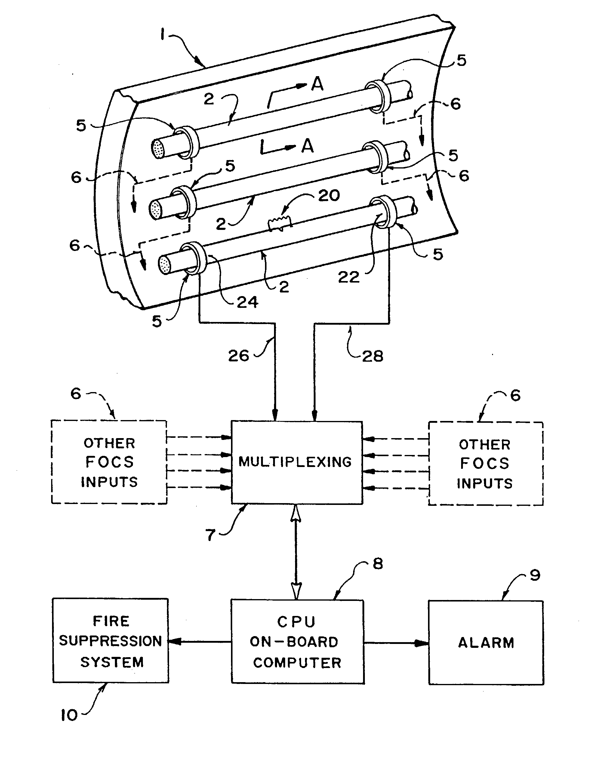
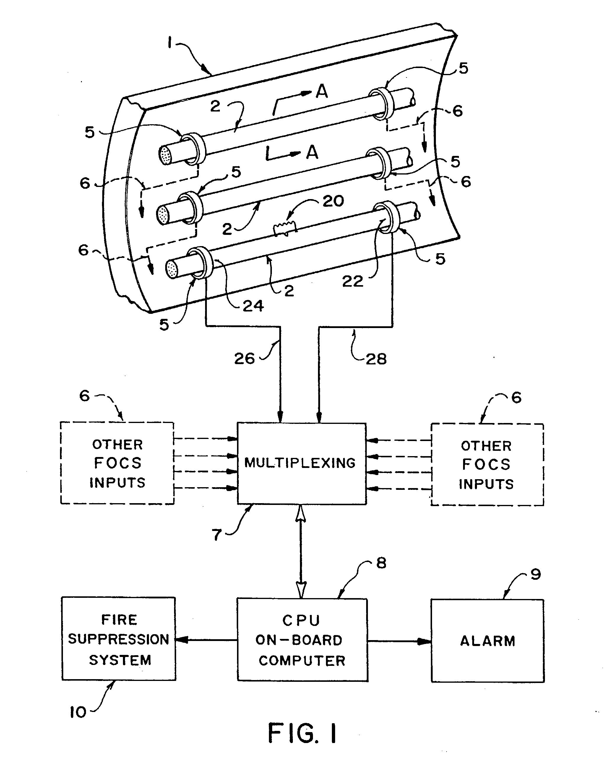
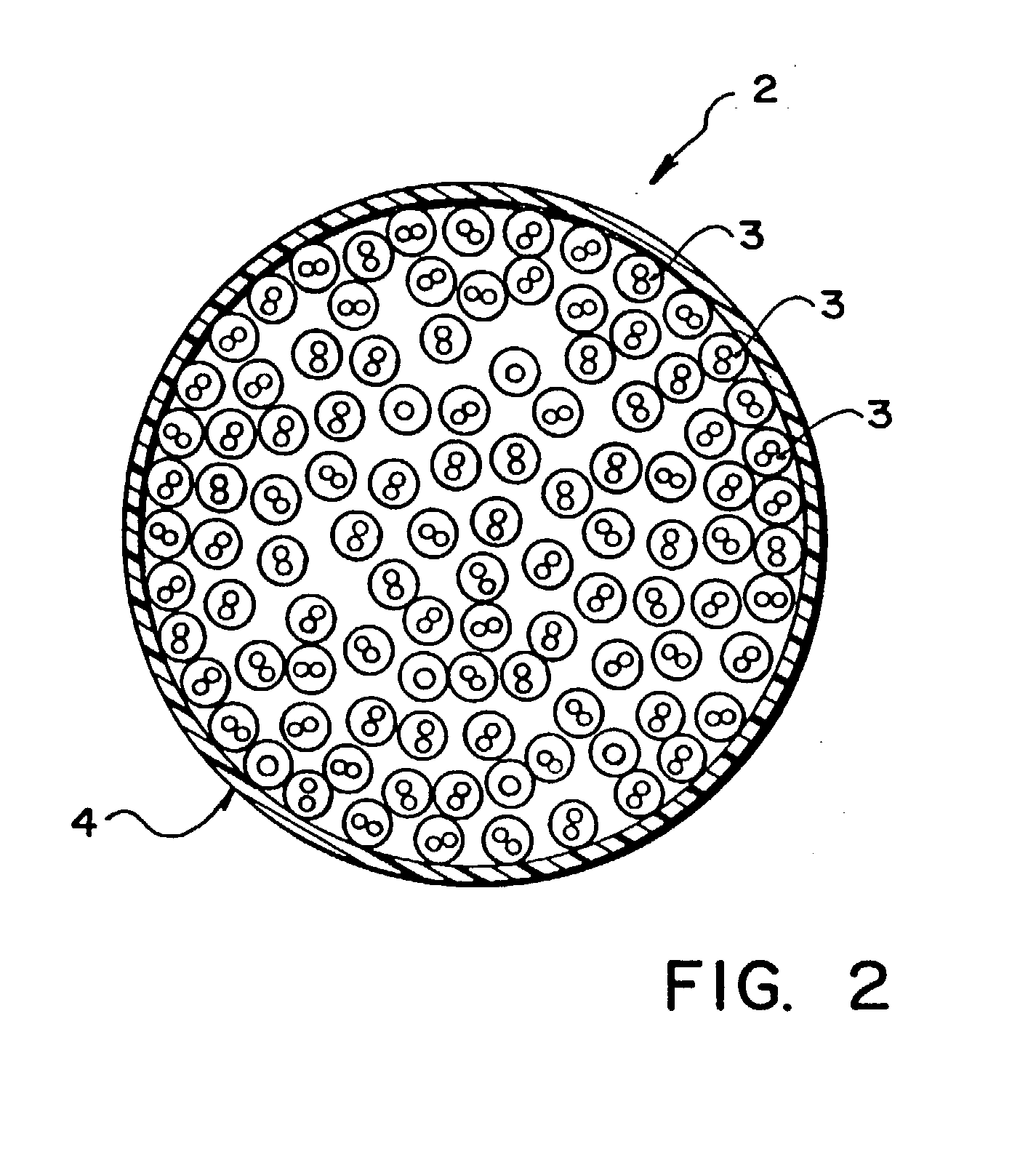
[0014] With reference to FIGS. 1 and 2, a standard aircraft wiring cable (not to scale), designated as 2, carries an electrical current, typically from a few milliamperes to 10's of amperes at 400 Hz. The cable consists of solid or stranded conductors of copper or aluminum, insulated with PTFE or Polyimide and twisted in pairs 3 and bundled into a large cable with an overall jacket 4. Power conductors are typically single core, whereas the control cables are twisted pairs. Some of these cables also carry direct current, although most carry the 400 Hz ac current generated by the airplane's generator. These cable bundles are mounted on the aircraft fuselage 1 or in cable trays and electronics bays inside the aircraft.

[0015] Extremely accurate optical current sensors 5, which may be fibre, slab or crystal are now available to measure the flow of current in the aircraft wiring. Such sensors have a resolution of 5.times.10.sup.-6 amperes and a bandwidth of dc to 50 kHz. Optical sensors o...


PUM


Abstract

Wiring in new and older aircraft use bundled insulated conductors that are subject to deterioration over time that can result in on-board fires, loss of in-flight control and eventual crashes of the aircraft. The present invention provides a diagnostic method which permits the on-line and non-destructive diagnosis of the insulation degradation in a portion of the wiring comprising: a) measuring the current flow at locations of the aircraft wiring utilizing an optical current sensor with a bandwidth of dc to 50 kHz; b) determining the current flow within a high frequency bandwidth; and c) analysing the results of the current flow differential determination and initiate the following: i) detect and locate the point of cable failure; ii) initiate an alarm annunciation; and iii) initiate an on-board sectionalized fire suppression system.

Description

[0001] The invention relates to a method for diagnosing degradation in electrical wiring, and more particularly to a method for diagnosing degradation in aircraft wiring insulation that can be incorporated into the on-board computer of an aircraft for fault location, early warning and initiation of the fire suppression system to prevent disastrous aircraft crashes.[0002] Control and power supply wiring on commercial and military aircraft and vehicles is provided by low voltage cables that are typically insulated with PTFE (polytetrafluoroethylene) or polyimide, sometimes referred to by the trade names Hypolon.TM. or Mylar.TM. insulation. PTFE offers high temperature resistance, high dielectric strength, fluid resistance and low smoke generation. Its weaknesses include susceptibility to cold flow and low dynamic cut-through resistance. Polyimide has all of the properties of PTFE but has improved resistance to dynamic cut-through. Unfortunately polyimide has been found to be susceptib...

Claims


Application Information

Patent Timeline
Patent Type & Authority Applications(United States)
IPC IPC(8): B64F5/60G01R31/00G01R31/02G01R31/08G01R31/12H02H1/00
CPCH02H1/0023G01R31/008G01R31/1272G01R31/088G01R31/1218G01R31/021G01R31/58
Inventor ORTON, HARRY E.
Owner ORTON HARRY E
Why Eureka
Try Eureka