

Heat discharger suitable for application to heat pipes
a discharger and heat pipe technology, applied in the field of heat dischargers, can solve the problems of increasing the heat generated by installed electronic equipment, creating the need to increase the size of the heat sink, and the inability to form sections corresponding to the heat pip
- Summary
- Abstract
- Description
- Claims
- Application Information
AI Technical Summary
Benefits of technology
Problems solved by technology
Method used
Image

Examples
embodiment 1
[0038] Embodiment 1
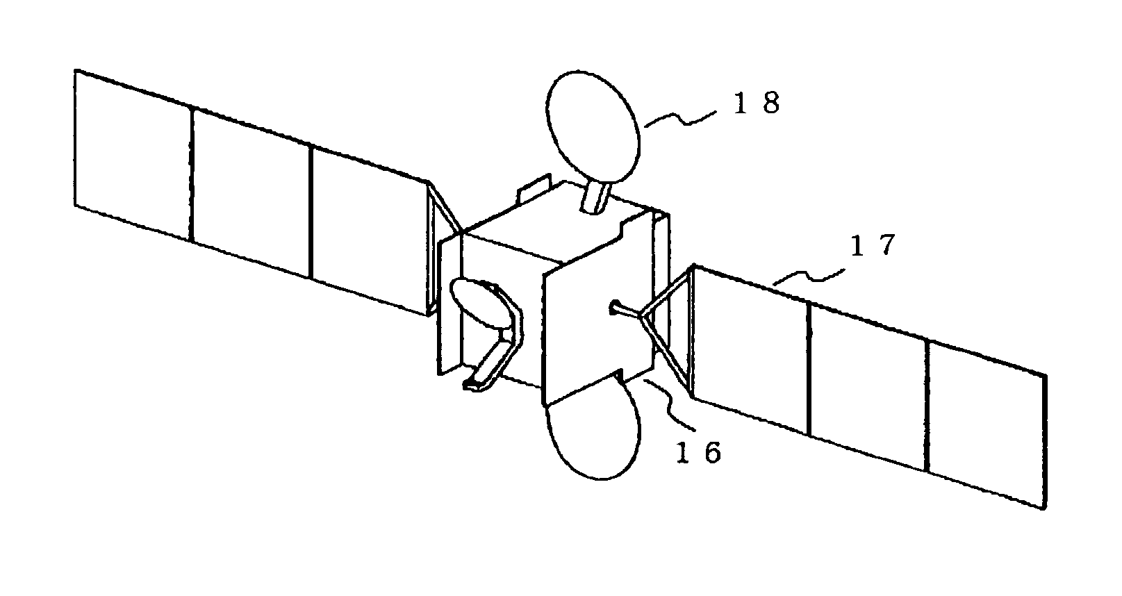
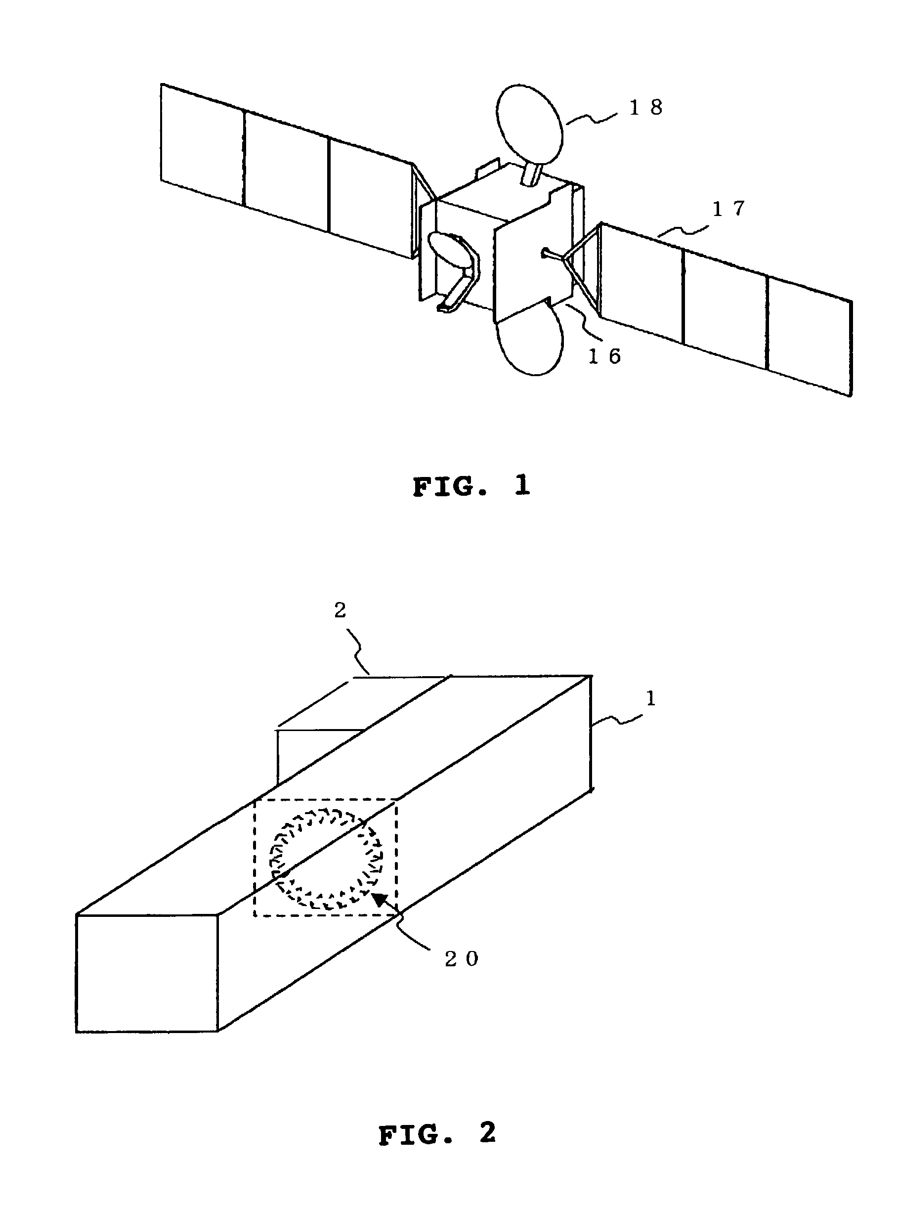
[0039] FIG. 1 shows a space satellite which comprises a container 16 in which electronic equipment for controlling the satellite are provided, a solar panel 17 for obtaining power by photoelectrically converting the sunlight, and an antenna 18 for transmitting electric waves to the earth.
[0040] Because the satellite must be lightweight and have high durability, a lightweight member is used which comprises a honeycomb structure in which a plurality of aluminum plates are formed with a predetermined gap to form a beehive-like structure. For the container 16, approximately 60 heat pipes are provided for heat conduction.
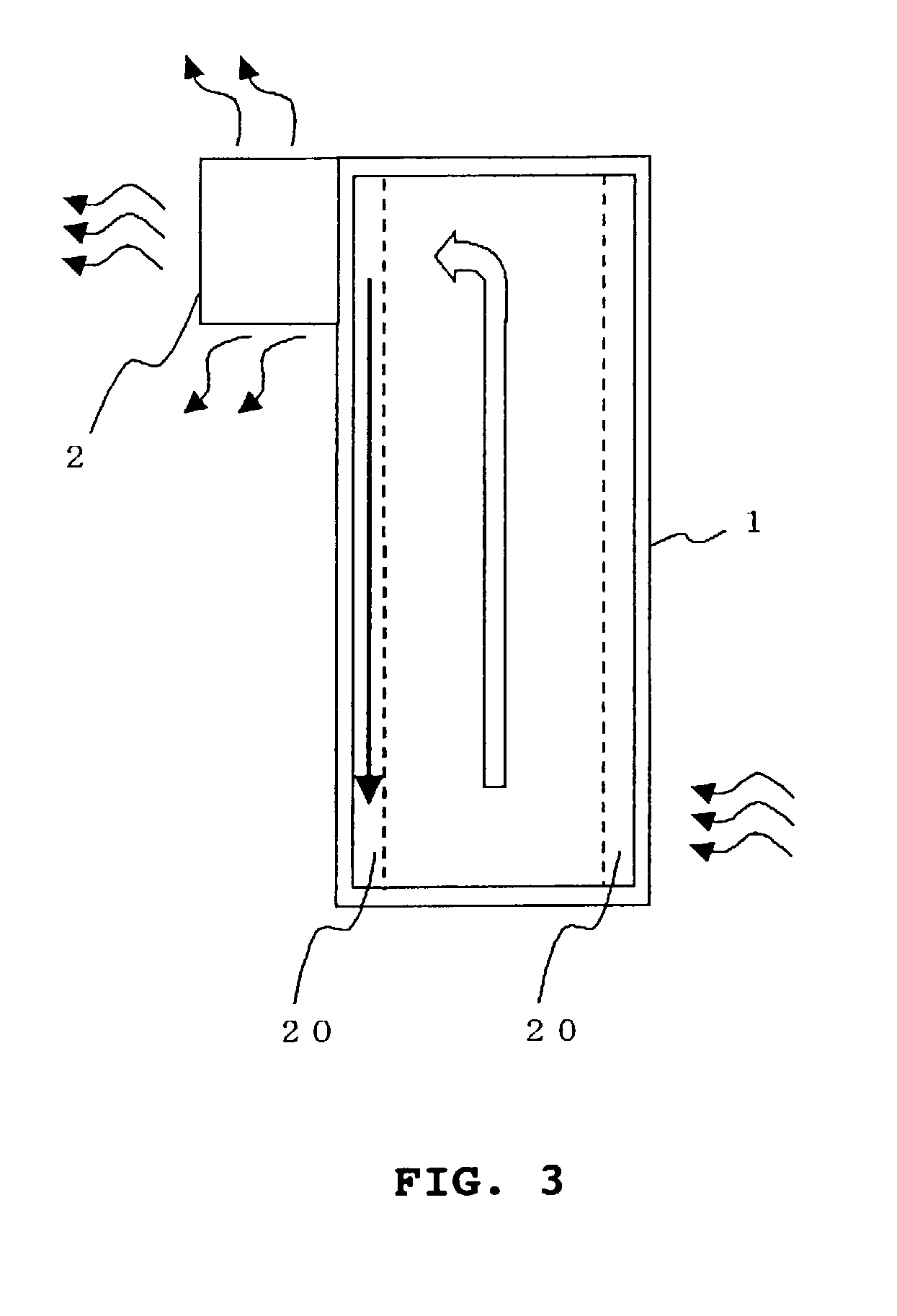
[0041] As shown in FIG. 2, the heat pipe 1 is made of a hollow aluminum member with a cross section having a quadrilateral outer periphery and a circular inner periphery. In the heat pipe 1, a plurality of channels or "wicks" 20 are provided on the inner surface along the longitudinal direction of the heat pipe 1 in a predetermined space in between. Al...
second embodiment
[0092] Second Embodiment
[0093] FIG. 16 shows a heat pipe according to a second embodiment of the present invention. The second embodiment differs from the first embodiment in that the heat sink 32 itself is made of copper. In the following, elements identical to those described in the first embodiment are assigned the same reference numerals and will not be described again. In the second embodiment, because the heat sink 32 is made of copper, the process for forming the copper coatings 3 on the heat sink 2 as described in the first embodiment can be omitted. Moreover, there is no possibility of the vent holes 30 of the heat sink 2 being filled by the copper coatings 3.
[0094] Also, because copper has a thermal conductivity of 300 [W / mK] or greater, which is greater than the thermal conductivity of aluminum, the thermal resistance can be approximately halved by forming the heat sink 32 from copper rather than from aluminum.
[0095] Because the heat pipe 1 is made of aluminum in the seco...
third embodiment
[0097] Third Embodiment
[0098] FIG. 17 shows a heat pipe according to a third embodiment of the present invention. The third embodiment differs from the first embodiment in that channels 12a and 12b which constitute a first connection section and projections 13a and 13b which constitute a second connection section are respectively provided at the bonding surface of the heat pipe 1a and at the bonding surface of the heat sink 2. The channels 12a and 12b and the projections 13a and 13b are formed so that they can engage respectively. The elements identical to those in the first embodiment are assigned the same reference numerals and will not be described again.
[0099] In the third embodiment, heat pipe 1a and heat sink 2 can be easily positioned for soldering because of the engagement between the channel 12a and the projection 13a and between the channel 12b and the projection 13b.
[0100] In the third embodiment, an example is described in which the channels 12a and 12b are provided on t...
PUM
| Property | Measurement | Unit |
|---|---|---|
| Angle | aaaaa | aaaaa |
| Thickness | aaaaa | aaaaa |
| Wettability | aaaaa | aaaaa |
Abstract
Description
Claims
Application Information