[0042] This propulsion system is simple, efficient, reliable and non-polluting. It will more than double the miles per gallon and cost less than half the amount to produce when compared with any vehicle of the same size and weight with an
internal combustion engine. It will accomplish this without using gears.[0043] The following mechanical items will not be used in the propulsion system: gears, camshafts, tappets and hydraulic valve lifters, push rods, valves and springs,
crankshaft, pistons and
wrist pins, timing chain drives and radiator, fans, v-belts and other rotary and reciprocating elements, spark-plugs, distributors and spark coils. Also not used is the power
train;
drive shaft, differential, axles, universal-joints, transaxles and final drive components. And
automatic transmission with
torque converter and planetary-gear. Electronically controlled automatic transmissions are too intricate. The so called "advanced technology", for
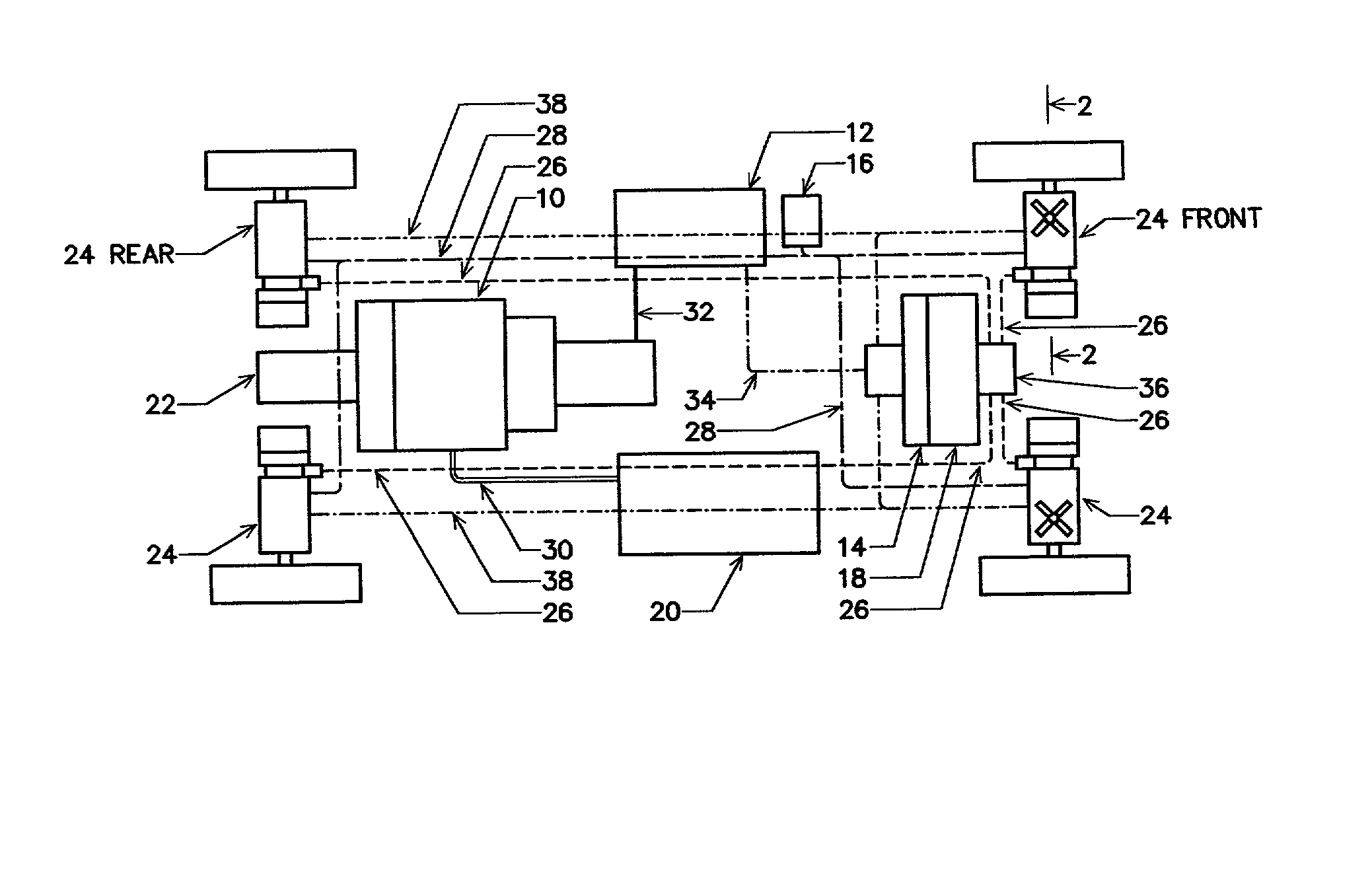
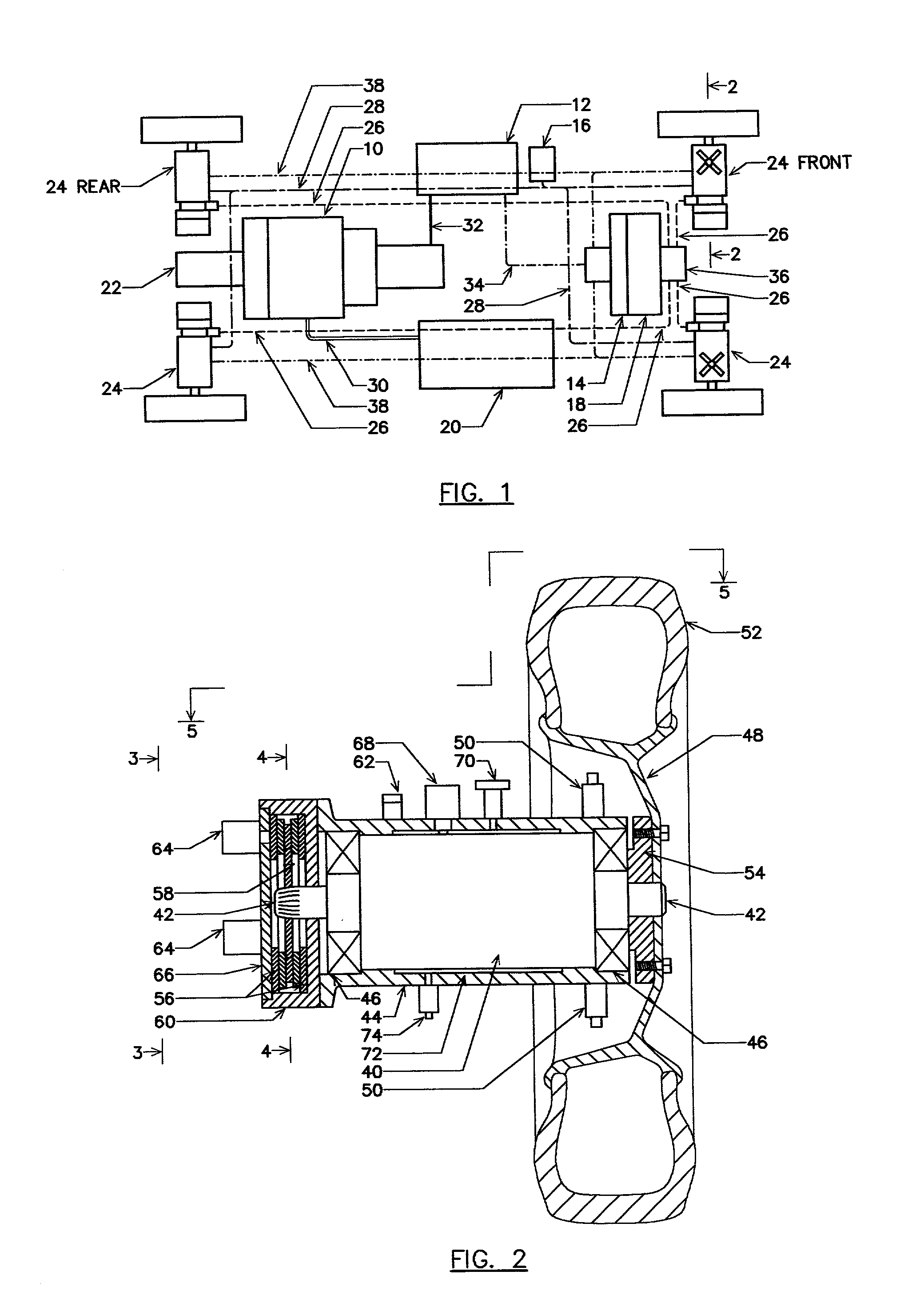
four wheel drive systems with "intelligence" will never come close to the efficient simplicity of the propulsion system advocated by this invention.[0044] The dynamic multi-axis load cells including the
vertical load vector, the torque and
angular velocity signals of the four wheels are monitored with a high degree of accuracy and routed thru the
central processing unit for controlling the wheels and displaying the system conditions at the comprehensive instrument panel to keep the driver informed. It's important. It adds to the safety of the driver and passengers, especially when the roads are wet and icy during the stormy months. The torque is instantly, constantly adjusted to make it even for the four wheels while maintaining a safe speed.[0045] The comprehensive instrument panel includes state of the art means for displaying and including audio means for keeping the driver informed. Of particular interest is the turbogenerator speed, "in" and "out" air-as temperature of the
turbine engine, the generator output, measured
volt-amp charging rate and the
battery charge level. A bar-graph readout cluster for each of the four wheel assemblies indicating position,
load vector, torque and
rotation velocity is included. Also included is the temperature of the cooling air for the motor-generators taken at the
cold air valve "in" and the pressure
relief valve "out". Also included is an
inclinometer for the off-the-road sportsman indicating safe and
rollover angles of risky mountain slopes.[0046] While I have illustrated and described a preferred embodiment of my invention, it is understood that this is capable of modification, and I therefore do not wish to be limited to the precise details set forth, but desire to avail myself of such changes and alterations as fall within the purview of the following claims:

