Evaporative desorption soil treatment apparatus and process

a technology of evaporative desorption and treatment apparatus, which is applied in the direction of drying machines, lighting and heating apparatus, furnaces, etc., can solve the problems of unburned hydrocarbons in the process exhaust gas, potential for spillage, and potential for leakage, and achieve the effect of reducing the risk of evaporation

Inactive Publication Date: 2003-08-07
BRADY PATRICK RICHARD +2
View PDF4 Cites 22 Cited by
  • Summary
  • Abstract
  • Description
  • Claims
  • Application Information

AI Technical Summary

Problems solved by technology

One risk associated with the storage and handling of petroleum hydrocarbons is the potential for spillages, during handling or the potential for leakage during storage.
This has the undesirable consequence of forming products of incomplete combustion, oxides of nitrogen, and other greenhouse gases as a by-product.
Combustion also has the potential to add unburned hydrocarbons to the process exhaust gas if strict control of the combustion process is not maintained.
The pile arrangement processes do not require energy-intensive material handling during treatment, however they may be characterized as requiring ...

Method used


Image

  • Evaporative desorption soil treatment apparatus and process
  • Evaporative desorption soil treatment apparatus and process
  • Evaporative desorption soil treatment apparatus and process

Examples


Embodiment Construction

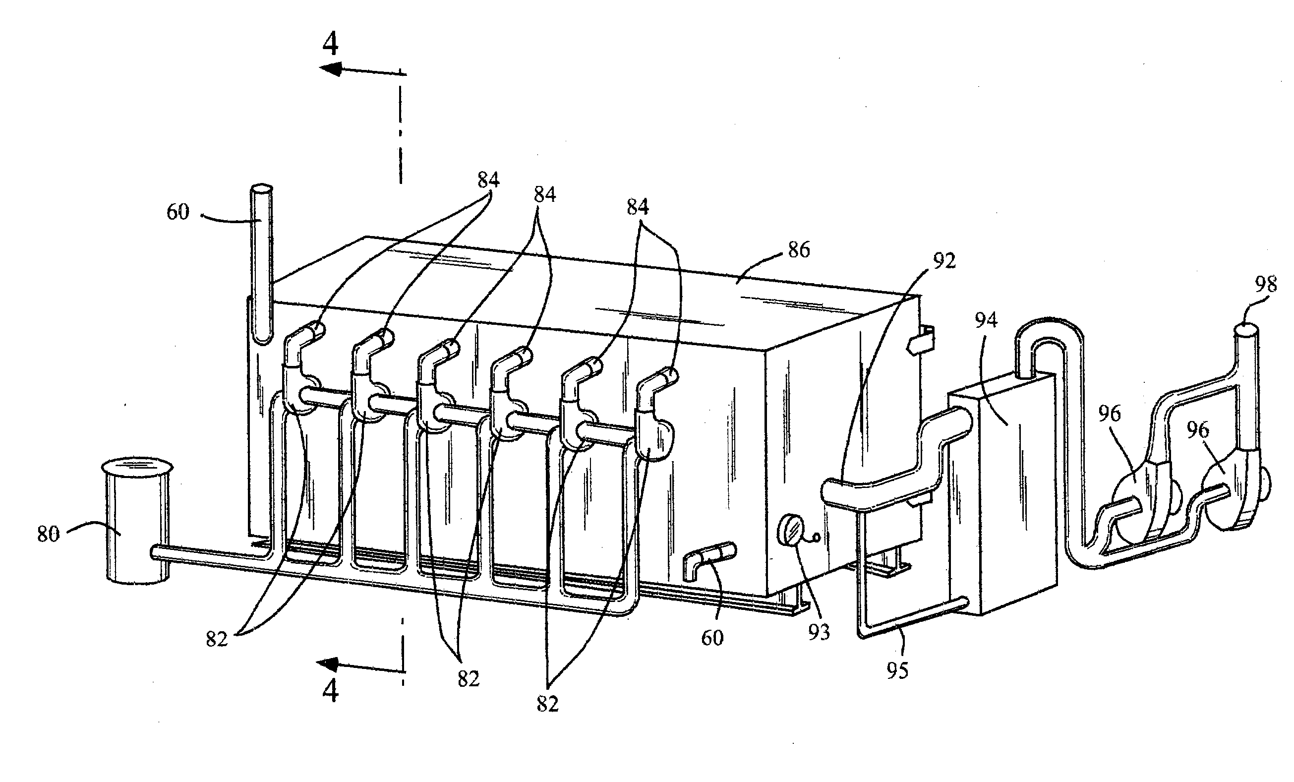
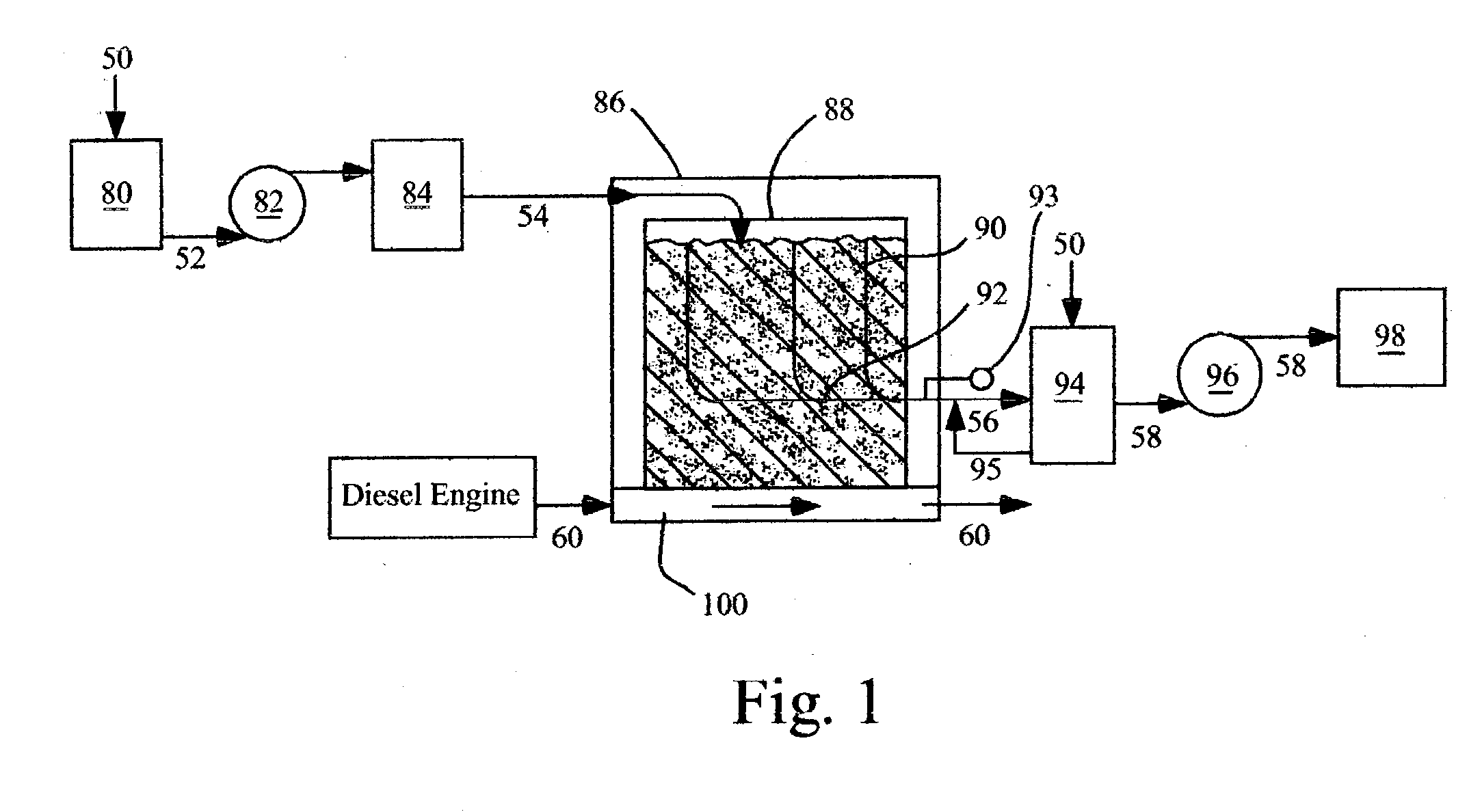
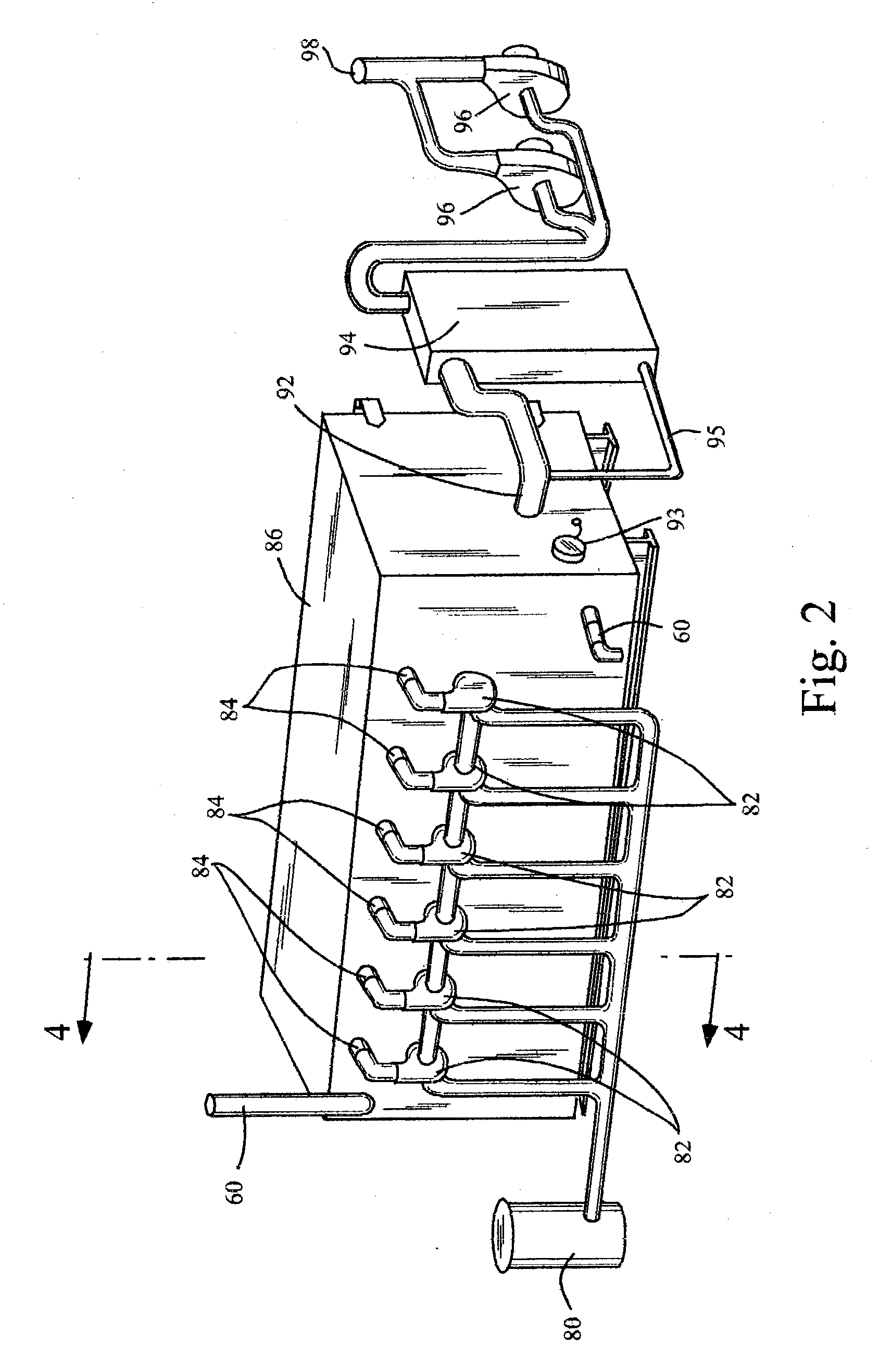
[0070] FIGS. 1 through 7 show the preferred embodiment of the evaporative desorption soil treatment process apparatus. FIG. 1 shows the treatment process method and FIGS. 2 through 7 show the arrangement of the apparatus. Treatment is done in a metal treatment chamber with internal thermal insulation as shown in FIG. 4. This figure shows the contaminated soil (90) that was dug from the contamination site, located in the open-top thermal conductive treatment vessel (88), which in turn is located in the treatment chamber (86). The soil is generally a mixture of soil and rocks. The contaminates in the soil and their concentrations may vary depending on the location they are dug from at the contaminated site.

[0071] The treatment vessel is a removable, sometimes called a roll-off, hopper modified to contain the gas exit pathway (92). FIG. 5 shows this pathway (92) is a slotted or perforated piping array located near the centerline of the treatment vessel at an elevation from the floor an...


PUM


Abstract

Treatment apparatus and a process for thermal desorption of hydrocarbon contaminants from excavated soil provides efficient contaminant removal by handling the soil in a thermally conductive treatment vessel that fits within an insulated treatment chamber. The soil is treated in this chamber with fresh air that is dried and electrically heated prior to contacting the treatment vessel. Excavating the soil directly into the treatment vessel allows the treated soil to be returned to the final disposition site in the same vessel, minimizing soil handling

Description

[0001] This application claims priority from Provisional Patent Application 60 / 354,572, "Evaporative Desorption Soil Treatment Apparatus and Process" filed on Feb. 06, 2002.STATEMENT REGARDING FEDERALLY SPONSORED RESEARCH AND DEVELOPMENT[0002] Not Applicable.REFERENCE TO A MICROFICHE APPENDIX[0003] Not Applicable.BACKGROUND OF THE INVENTION--FIELD OF THE INVENTION[0004] This invention relates to a process and apparatus for thermal desorption of contaminates from a mixture of soil and rocks using desiccated, electrically-heated fresh air to treat the soil and rocks which have been excavated and placed in a thermally conductive treatment container which is then placed in a thermally insulated treatment chamber. The fresh, hot, desiccated air is drawn through the soil treatment container, cooled, and released; or discharged to a treatment system, as required or needed, prior to release to the atmosphere.BACKGROUND OF THE INVENTION--DESCRIPTON OF RELATED ART[0005] The use of petroleum h...

Claims


Application Information

Patent Timeline
IPC IPC(8): B09C1/06F26B3/00F26B21/06F26B25/06
CPCB09C1/06F26B25/063F26B21/06F26B3/00
Inventor BRADY, PATRICK RICHARDBRADY, JOHN LEEDENISON, HARVEY ADNA
Owner BRADY PATRICK RICHARD
Why Eureka
Try Eureka