Method for assembling conductive segments of a rotor winding or stator winding in a rotary electric machine

a technology of rotary electric machines and conductive segments, which is applied in the manufacture of stator/rotor bodies, soldering apparatus, magnetic bodies, etc., can solve the problems of increasing production costs, limiting the quantity of heat released outside welding zones, and difficult to envisage high-speed production lines, etc., to achieve rapid, simple and economical assembly, and reduce the cost of segments. , the effect of high quality

Inactive Publication Date: 2003-08-28
VALEO EQUIP ELECTRIC MOTEUR
View PDF4 Cites 22 Cited by
  • Summary
  • Abstract
  • Description
  • Claims
  • Application Information

AI Technical Summary

Benefits of technology

0015] It is thus no longer necessary to provide a preliminary stripping stage, such as, for example, mechanical stripping of the layer of electrically insulating material. Moreover, the outlay incurred for the assembly of the segments is considerably reduced. The solution is thus rapid, simple and economical.
0016] Surprisingly, it has furthermore been found that when the wel

Problems solved by technology

This limits the quantity of heat released outside the welding zones.
However, this technique has one major disadvantage, inasmuch as it requires preliminary stripping of the free ends of the conductive segments to be welded, considerably increasing the costs of production, and is difficult to envisage in high-speed production lines inasmuc

Method used


Image

  • Method for assembling conductive segments of a rotor winding or stator winding in a rotary electric machine
  • Method for assembling conductive segments of a rotor winding or stator winding in a rotary electric machine
  • Method for assembling conductive segments of a rotor winding or stator winding in a rotary electric machine

Examples


Embodiment Construction

OF THE INVENTION

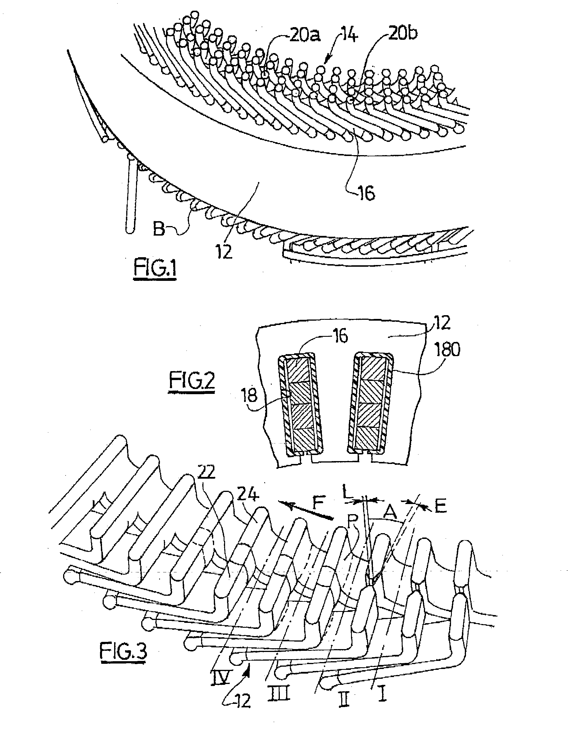
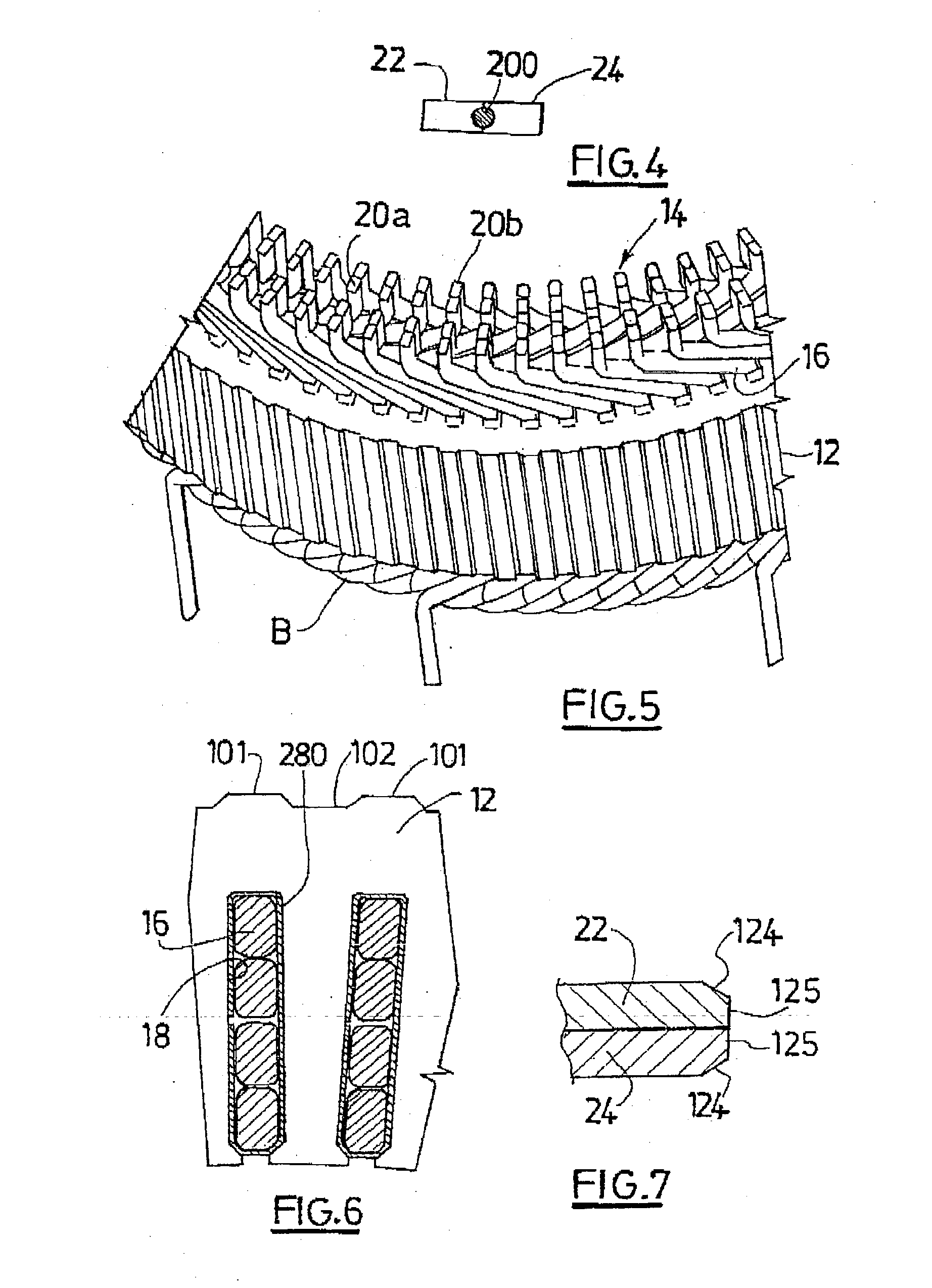
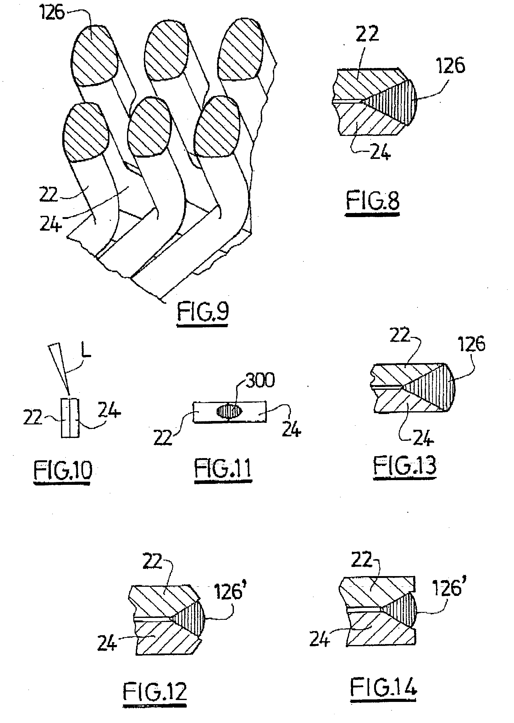
[0039] In the explanation which follows, the assembly of a stator winding of a motor-vehicle alternator will be described. However, the invention also applies, where appropriate, to the assembly of a rotor winding of an alternator and, in a general way, to the assembly of a rotor or a stator of a rotary electrical machine.

[0040] As is known, a conventional motor-vehicle alternator includes a rotor firmly fixed to a rotor shaft, the axial ends of which are supported in rotation by a hollow support designed to be mounted on a fixed part of the motor vehicle. On the inside, at its outer periphery, this support carries a stator, described below, surrounding the rotor. In this alternator, the rotor is shaped to form an inductor, while the stator is shaped to form an armature.

[0041] The support includes two parts, referred to respectively as a front bearing and a rear bearing. Each bearing features a central receptacle for mounting a ball bearing, in which the relevant end...


PUM

PropertyMeasurementUnit
Angleaaaaaaaaaa
Electrical conductoraaaaaaaaaa
aaaaaaaaaa

Abstract

The inventive method of assembling conductive segments (16) of a rotor winding or a stator winding in a rotary electric machine comprises the following stages: insertion of the conductive segments (16) into slots made in a core (12) of the rotor or stator, whereby the free ends of the conductive segments protrude beyond the latter, and welding of the free ends of the conductive segments in groups of two in order to form a winding (14) around the rotor or stator. The conductor statements are both made of wire which is electrically conductive and coated with an electrically insulating material. The coating of electrically insulating material is removed in the welding zone of the conductive segments by the means used for welding the latter. The invention can be used for conducting segments of a rotor or stator winding in an alternator in a motor vehicle.

Description

[0001] The present invention relates to a process for assembling conductive segments of a rotor or stator winding of a rotary electrical machine.[0002] More particularly, the invention concerns a process for assembling conductive segments of a rotor or stator winding of a motor-vehicle alternator.PRIOR ART[0003] In a conventional configuration, the stator windings of a motor-vehicle alternator are formed by using pre-formed conductive winding segments in the form of a U, which are inserted, by their base, into slots formed in a core of the stator in such a way that the mutually opposite free-end zones of the conductive segments project beyond the latter, and by welding the conductive segments in pairs to form continuous wound components around the core.[0004] An assembly technique of this kind is described, for example, in the document EP-A-1 043 828. According to this technique, the conductive segments are generally welded using arc-type welding, e.g. of the TIG type, by creating a...

Claims


Application Information

Patent Timeline
IPC IPC(8): H02K3/04H02K3/12H02K15/00H02K15/08
CPCH02K15/0056H02K15/0081Y10T29/49071Y10T29/53143Y10T29/49009Y10T29/49012Y10T29/49011H02K3/12
Inventor LENOIR, ROMARICARRIGHI, SEBASTIENEVEN, DENISHEVIA, THIERRY
Owner VALEO EQUIP ELECTRIC MOTEUR
Why Eureka
Try Eureka