
Compact turbocharger
a turbocharger and compact technology, applied in the field of turbochargers, can solve the problems of reducing the mechanical efficiency of turbochargers, and the differential speed between the sleeve bearing and the rotor is the very high rotative speed of the rotor, so as to reduce the thermal expansion of the shaft, and increase the protection of the anti-friction bearings
- Summary
- Abstract
- Description
- Claims
- Application Information
AI Technical Summary
Benefits of technology
Problems solved by technology
Method used
Image

Examples
Embodiment Construction
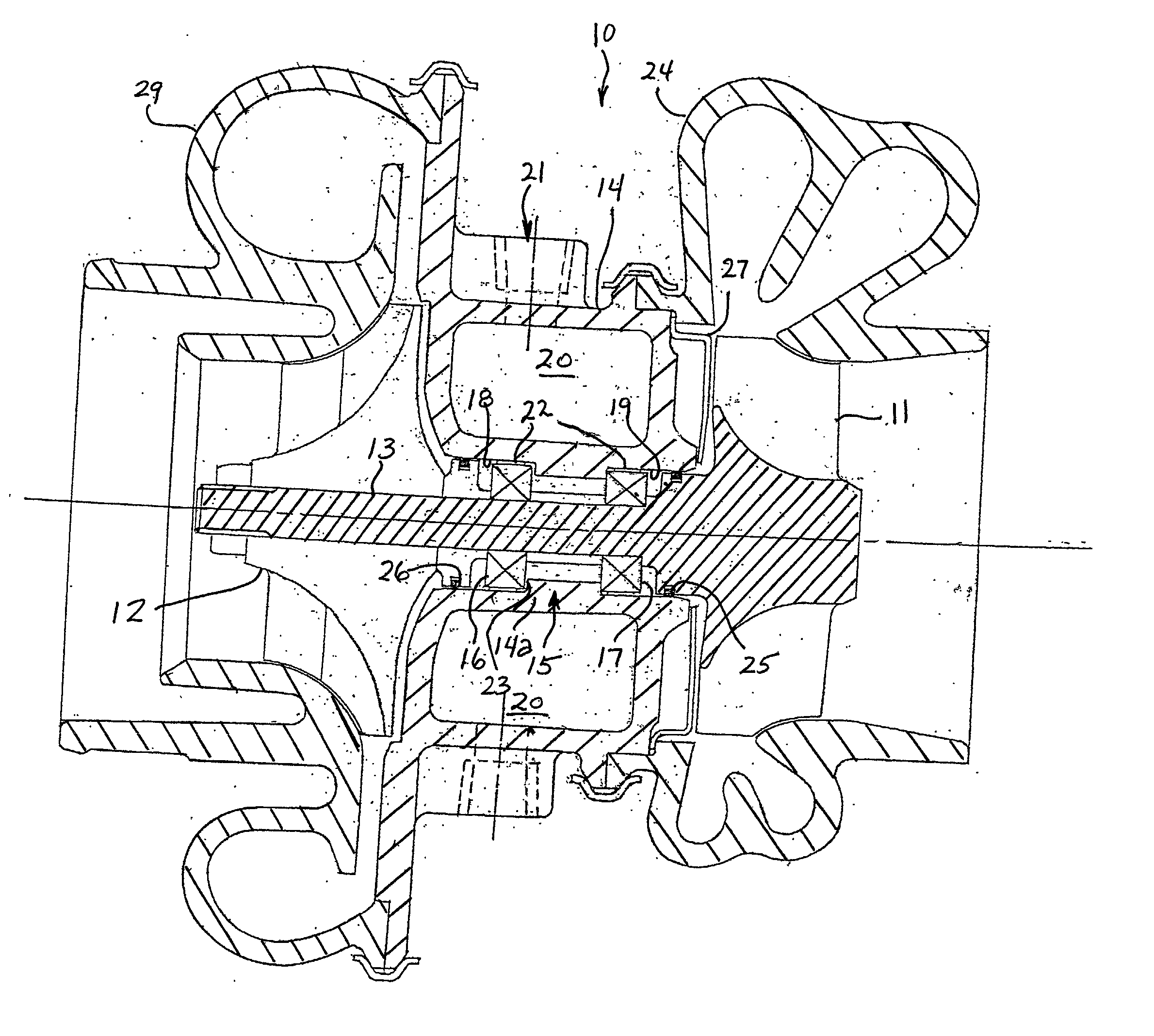
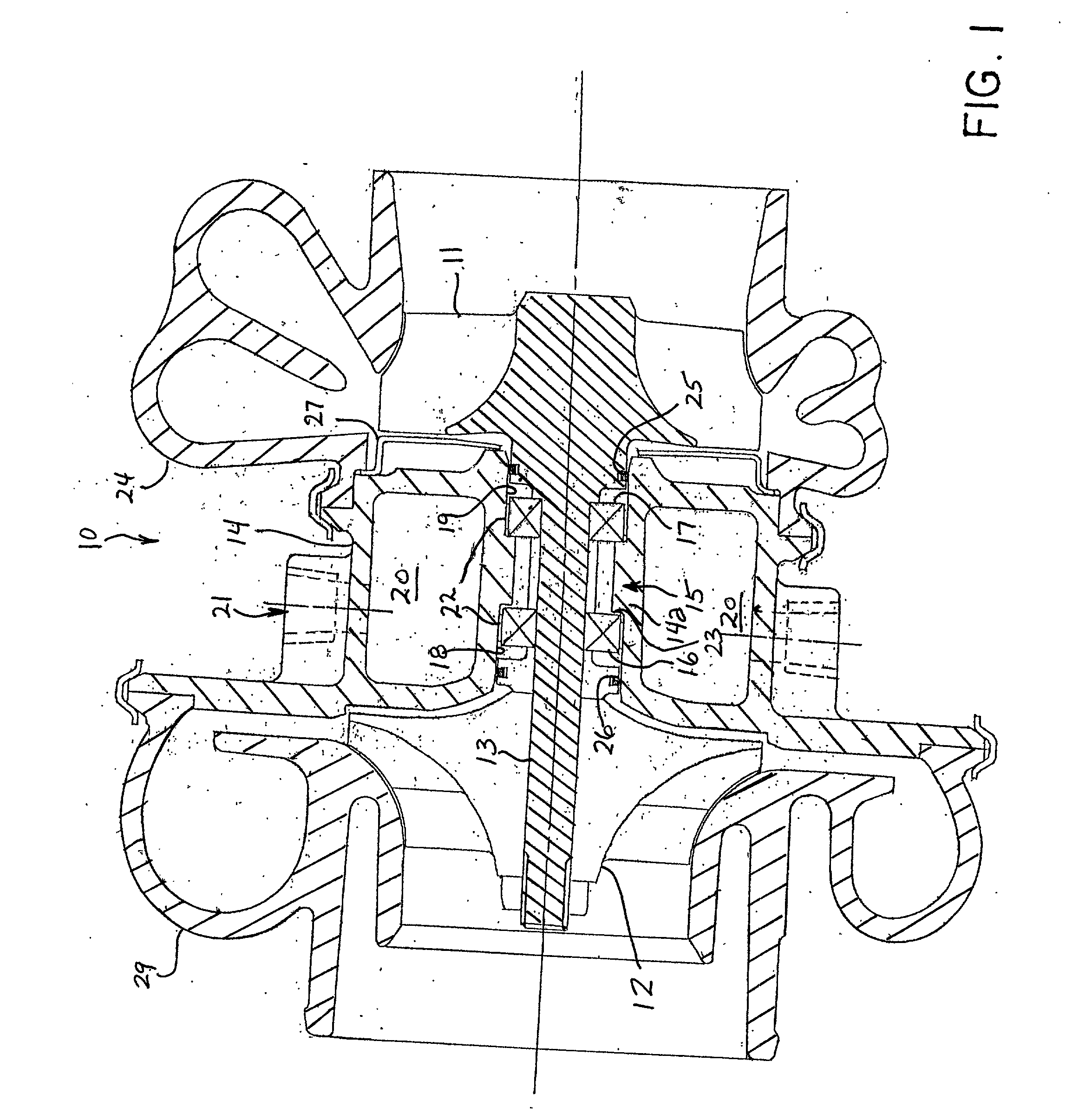
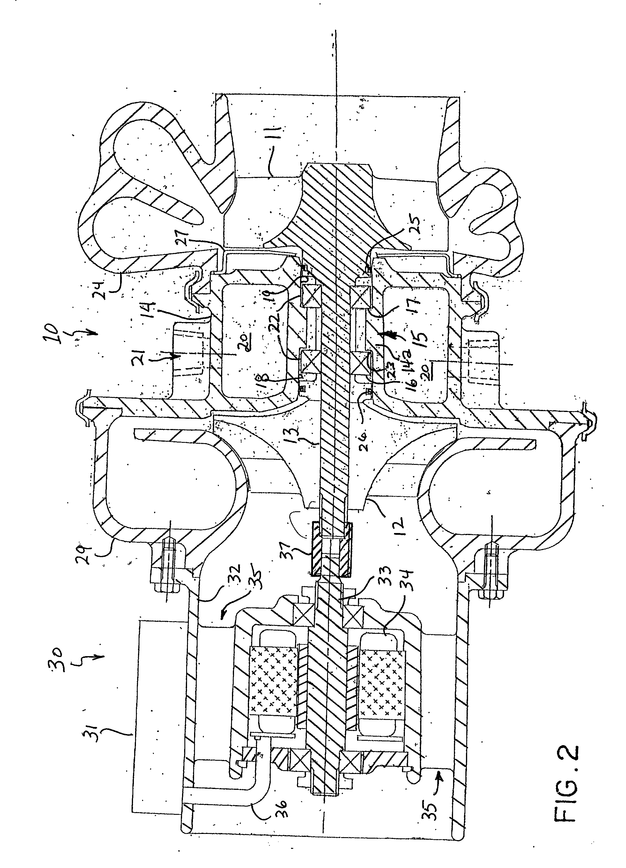
[0017] The invention, as illustrated in FIG. 1, provides a compact turbocharger 10 including an exhaust gas-driven turbine wheel 11 and a compressor wheel 12 on a rotatable shaft 13 carried by a bearing housing 14 and bearing system 15 that includes a pair of anti-friction bearings 16, 17.
[0018] The bearing housing 14 comprises an inner bearing-engaging portion 14a with two bearing engagement surfaces 18, 19 for engagement with the outer races of the anti-friction bearings 16, 17. As illustrated in FIG. 1, the bearing housing 14 forms a coolant jacket 20 for cooling the two bearing engagement surfaces 18, 19 and maintaining satisfactory operating temperatures of the anti-friction bearings 16, 17. With the invention, the ball bearings 16, 17 can be maintained at temperatures of 300.degree. F. and less under the most severe high temperature operating conditions of the turbocharger. The bearing housing 14 has an inlet 21 for coolant that may be connected with the coolant system of an i...
PUM
 Abstract
Description
Claims
Application Information