

Drive apparatus for PWM control of two inductive loads with reduced generation of electrical noise
- Summary
- Abstract
- Description
- Claims
- Application Information
AI Technical Summary
Benefits of technology
Problems solved by technology
Method used
Image

Examples
first embodiment
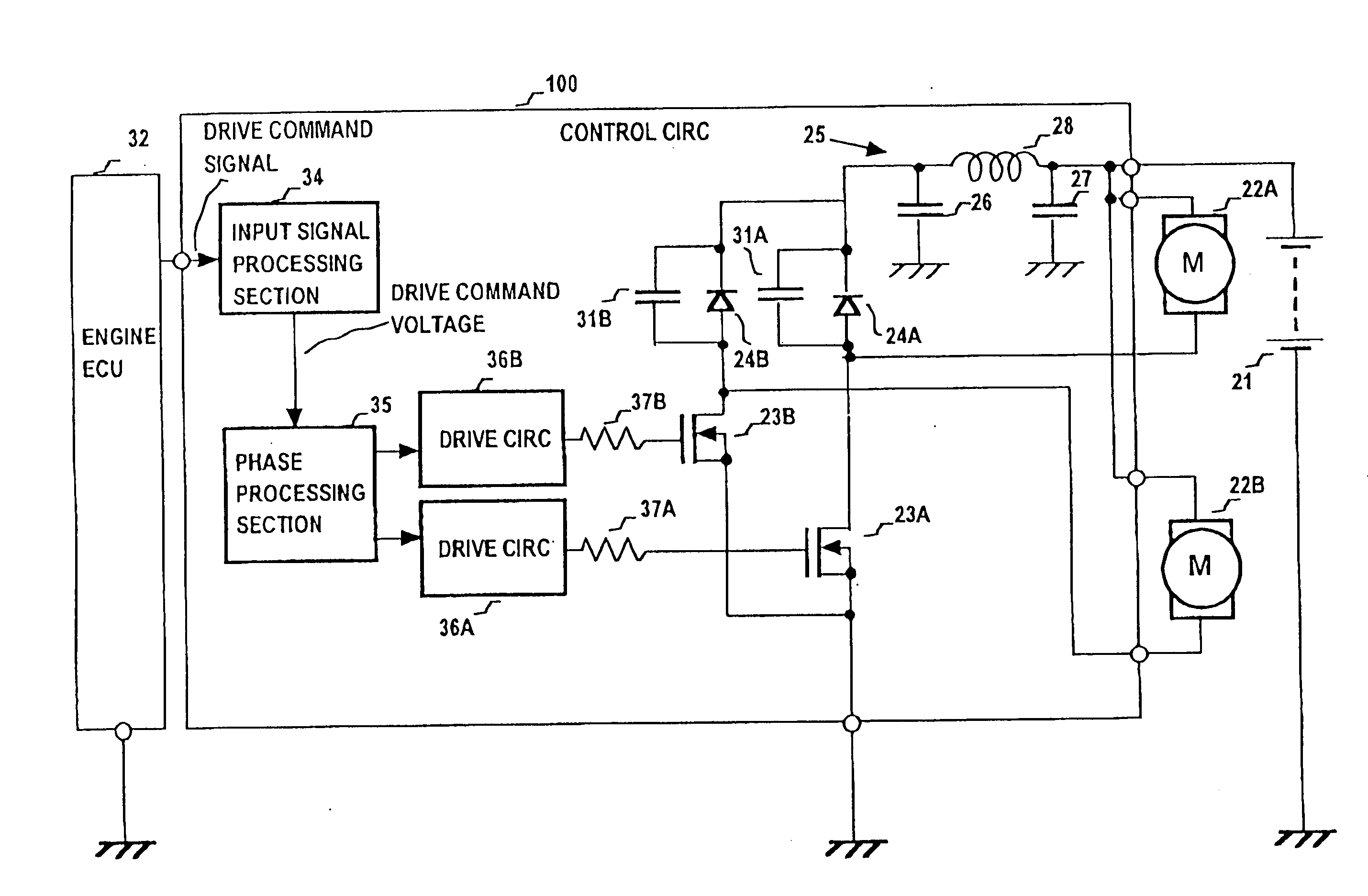
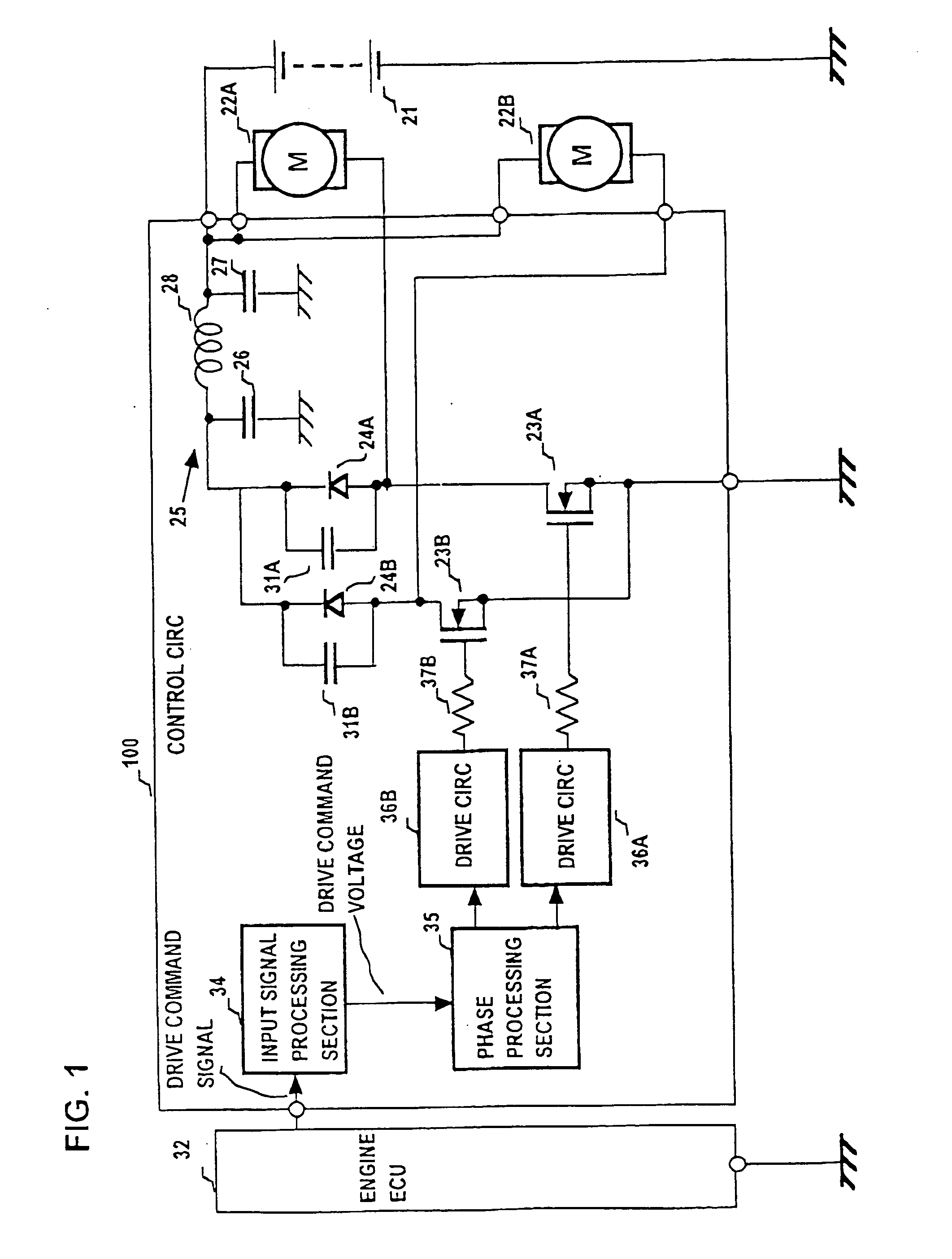
[0063] The motors 122A, 122B are driven by PWM operation by the control circuit 110, with the motor 122A and MOS FET 23A being connected in series between the (positive) potential of the battery 21 and ground potential, and the motor 122B and MOS FET 23B similarly connected in series between the positive potential of the battery 21 and ground potential. The drains of the MOS FETs 23A, 23B are connected through respective diodes 24A, 24B to one side of the .pi. filter 25, with the other side of the filter 25 connected to the positive potential of the battery 21, and with the diodes being connected in a direction such as to be reverse-biased when the corresponding one of the MOS FETs 23A, 23B is set in the on (i.e., conducting) state. Capacitors 31A, 31B for noise suppression are respectively connected in parallel with the diodes 24A, 24B. The n filter 25 is formed of a coil 28 and capacitors 26, 27 as shown. These components correspond in function to the correspondingly numbered comp...
second embodiment
[0080] FIG. 12 shows an example of graphs of the relationship between (average) drive voltage applied to a motor and resultant air flow rate from a fan driven by the motor, for the case of a 100 W and a 160 W motor respectively. As shown, for example the air flow rate produced by the fan of the 160 W motor is 2000 m.sup.3 / h with a drive voltage of approximately 5.8 V, whereas it is necessary to apply a drive voltage of 7.0 V to the 100 W motor in order to achieve the same air flow rate. Assuming that the 160 W motor and 100 W motor respectively correspond to the motors 122A, 122B of the second embodiment, it can be understood that the amplification factor of the amplifier 216B can be preset by adjusting the values of the resistors 218B, 219B, 221B, 223B appropriately. That is to say, the amplification factor would be preset such that when a drive voltage of 5.8 V is being supplied to the motor 122A, the duty ratio of switching the FET 23B is increased relative to that of the FET 23A...
PUM
 Abstract
Description
Claims
Application Information