Method and apparatus for removing hydrocarbons from water

a technology of hydrocarbons and water, applied in the direction of multi-stage water/sewage treatment, instruments, separation processes, etc., can solve the problems of large amount of natural gas produced, adversely affecting marine life, and numerous drawbacks, so as to reduce the content of hydrocarbons, encourage cyclonic flow, and encourage cyclonic flow

Inactive Publication Date: 2004-02-26
AMCOL INTERNATIONAL CORPORATION
View PDF10 Cites 32 Cited by
  • Summary
  • Abstract
  • Description
  • Claims
  • Application Information

AI Technical Summary

Benefits of technology

0026] A method for reducing hydrocarbon content in a stream of production water is also disclosed. The method comprises tangentially injecting the production water into a cylindrical vessel to encourage cyclonic flow within the vessel, tangentially injecting the flow of recycled water from the vessel and sparge gas into the vessel at a level below a point where the production water is injected and to further encourage cyclonic flow within the vessel, allowing the sparge gas and hydrocarbon-rich water to migrate to a top surface of the circulating liquid within the vessel, purging the hydrocarbon-rich water at a top surface of the circulating liquid and along a central axis of the vessel, and purging hydrocarbon-lean water from a lower point in the vessel below where the flow of recycled water and sparge gas are injected into the vessel.

Problems solved by technology

This "produced water" is contaminated with residual or hydrocarbons and therefore is a substantial waste stream.
These huge volumes of produced water must be treated before they are returned to the sea because they contain significant amounts of hydrocarbon contaminants.
While a 20-40 ppm hydrocarbon content meets current regulations, it is been found that the discharge of production water with the above-noted trace impurities can adversely affect marine life.
Often, large amounts of natural gas are produced with crude oil.
While the HIGF separators are commonly used, they suffer from numerous drawbacks.
Many older platforms, where space is limited, cannot be outfitted with such separators.
Further, HIGF separators to date have not been able to reduce hydrocarbon concentration below an approximately 20 ppm threshold level.
HIGF separators are also susceptible to wave motion experienced by modern platforms.
This rolling causes the water inside the HIGF separators to form waves, which makes skimming hydrocarbons from the water surface difficult and often ineffective.
Further, intense wave motion will cause some units to shut down thereby creating disruptions in platform production because of a lack of storage capacity for untreated production water.
Also, because of their large size, in the event the production water output exceeds expectations, operators are unable to expand capacity by adding additional HIGF separators because of a lack of available floor space.
Further, the flow rate of production water from a well can vary greatly and HIGF separators operate more efficiently in a steady state condition and the efficiencies of these systems is compromised with varying input flows.
Still further, HIGF separators are limited in their ability to treat water with higher hydrocarbon concentrations, i.e. greater than 300 ppm.
Their ability to remove partially soluble components such as alkyl phenols and polyaromatic hydrocarbons is extremely limited as these components are relatively soluble in water and do not respond to gas / bubble contact.
As noted above, these compounds are extremely harmful to marine life.
However, this apparatus is suitable only for preliminary separation of oil from production water and does not reduce the hydrocarbon content in the production water to a level acceptable for discharge or more intensive treatment such as filtering with organophillic clays.
However, it has been found that when the hydrocarbon content of the production water inputted into an organophilic clay containing vessel exceeds 100 ppm, the available adsorbing sites on the clay are readily used up and the cartridges must be replaced frequently, thereby increasing costs and creating time delays.
The vortex creating apparatus of WO 99 / 00169 is not suitable as a sole pre-treatment of production water upstream of an organophilic clay filtering apparatus.

Method used


Image

  • Method and apparatus for removing hydrocarbons from water
  • Method and apparatus for removing hydrocarbons from water
  • Method and apparatus for removing hydrocarbons from water

Examples


Embodiment Construction

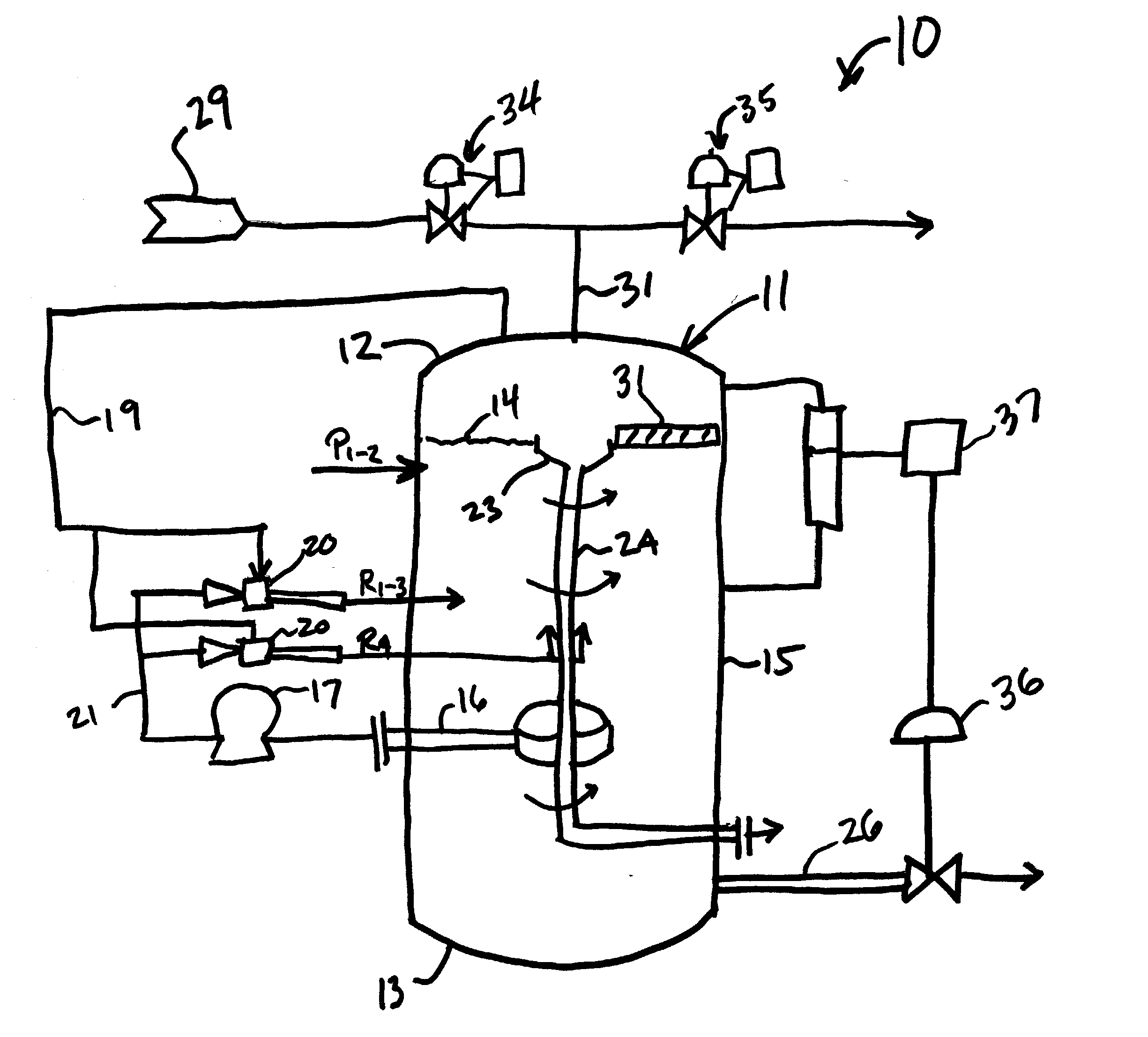
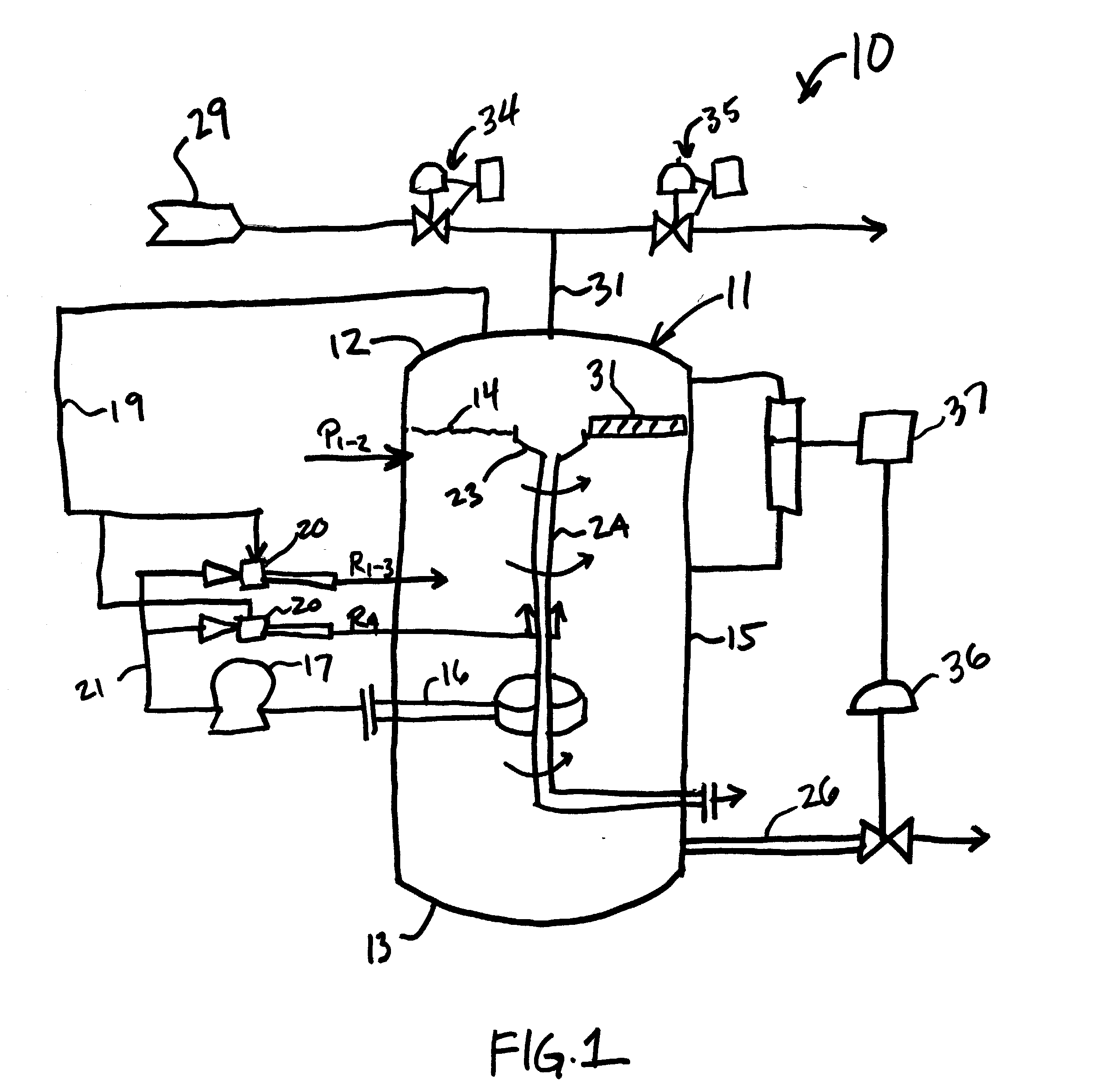
[0038] Turning to FIG. 1, an improved apparatus 10 is disclosed which has a vertical orientation and can provide a superior substitute for the currently employed HIGF separators. The apparatus 10 includes a vessel 11 which has a height to width ratio ranging from about 5.0 to about 1.5, preferably about 2.5. One suitable size for the vessel 11 is a height of 10 feet and a width or diameter of 4 feet.

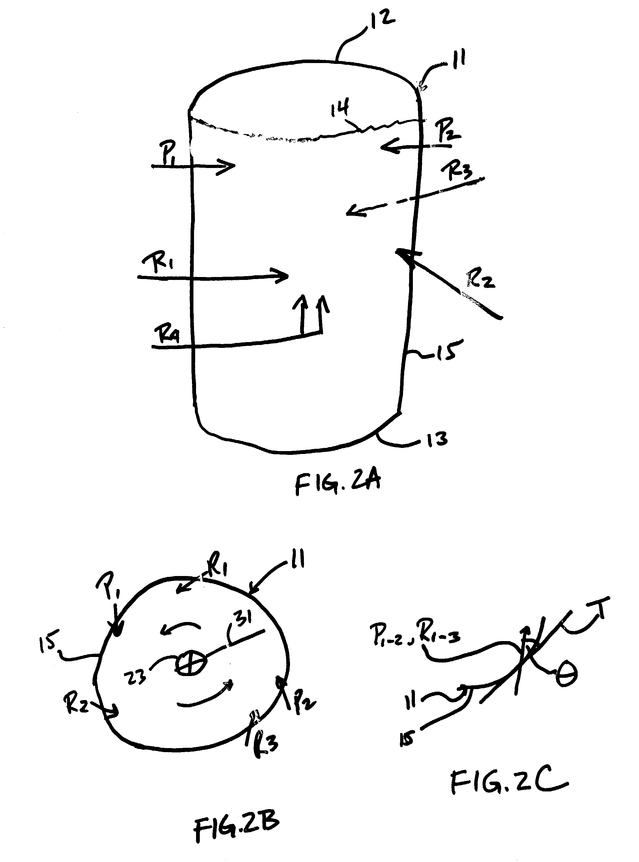
[0039] Production water is introduced into the vessel through one or more input inlets indicated at P.sub.1, P.sub.2 in FIGS. 1 and 2A-2C. It will be noted that the number of production water input inlets can vary in anywhere from 1 to 3 or 4 and that the use of two production water input inlets P.sub.1, P.sub.2 as shown in FIGS. 1 and 2A-2C is an example, albeit a preferred example. Referring to FIGS. 2A-C, it will be noted that the production water input inlets P.sub.1, P.sub.2 are directed "tangentially" with respect to the vessel 11. That is, the nozzles P.sub.1, P.sub.2 are directed...


PUM

PropertyMeasurementUnit
lengthaaaaaaaaaa
angleaaaaaaaaaa
diameteraaaaaaaaaa

Abstract

An improved production water treatment system and method are disclosed. The treatment apparatus includes a vertically oriented vessel with tangentially disposed injection nozzles including one or more injection nozzles for the introduction of production water and one or more injection nozzles for the introduction of recycled water from the vessel and a sparge gas. The tangential orientation of the injection nozzles creates a cyclonic flow within the vessel for improved sparge gas bubble/hydrocarbon contact. A hydrocarbon-rich layer migrates to the top surface of the liquid in the vessel where it is removed about a center axis of the vessel. The resulting hydrocarbon-lean production water has a sufficiently low hydrocarbon content that it is eligible for more intensive processing, such as with organophillic clay cartridges.

Description

[0001] An apparatus and method for separating hydrocarbons and other organic materials from water, such as acidflow back water, completion fluid water, produced water and rain water collected from off-shore oil drilling and production platforms, are disclosed. More specifically, an apparatus is disclosed for pre-treating these production waters generated on off-shore oil drilling and production platforms by injecting the production water in an enclosed vessel and generating a cyclonic flow within the vessel. Recycled water from the vessel and a sparge gas are also tangentially injected into the vessel to further encourage the cyclonic flow. The gas and hydrocarbon-rich water migrate towards the top surface of the liquid in the vessel and towards the axial center of the vessel where the hydrocarbon-rich water is purged. Hydrocarbon-lean water is then purged from a bottom section of the vessel and discharged or processed further.BACKGROUND OF THE RELATED ART[0002] During crude oil pro...

Claims


Application Information

Patent Timeline
Patent Type & Authority Applications(United States)
IPC IPC(8): B01D17/02B03D1/14C02F1/00C02F1/38C02F9/00C02F9/02
CPCB01D17/0202B03D1/1456C02F1/38C02F9/00C02F2101/32C02F2301/024C02F2301/026B03D1/1418B03D1/247B03D1/1475B03D1/1462B01D17/0205B01D17/0208B01D17/0214B01D17/0217C02F1/28
Inventor SMITH, JEFFREY J.DARLINGTON, JERALD W. JR.OCCHIPINTI, JOHNJUST, GERARD A.
Owner AMCOL INTERNATIONAL CORPORATION
Why Eureka
Try Eureka