
Load recognition and series arc detection using bandpass filter signatures

a filter signature and load recognition technology, applied in the field of arc fault detection system and method, can solve problems such as corroded, worn or aged wiring, circuit breakers that interrupt an electric circuit, and conventional circuit breakers to trip, so as to achieve reliable detection of arc fault conditions

Inactive Publication Date: 2004-03-04
SCHNEIDER ELECTRIC USA INC
View PDF99 Cites 51 Cited by
  • Summary
  • Abstract
  • Description
  • Claims
  • Application Information

AI Technical Summary

Benefits of technology

[0012] It is an object of the present invention to provide an arc fault detection system and method which reliably detects arc fault conditions which may be ignored by conventional circuit interrupters.
[0013] Another object of the invention is to provide an arc fault detection system which utilizes a minimum number of highly reliable electronic signal processing components, such as a microcontroller, to perform most of the signal processing and analyzing functions, so as to be relatively simple and yet highly reliable in operation.

Problems solved by technology

Typically, circuit breakers interrupt an electric circuit due to a disconnect or trip condition such as a current overload or ground fault.
A ground fault trip condition is created by an imbalance of currents flowing between a line conductor and a neutral conductor which could be caused by a leakage current or an arcing fault to ground.
However, arcing faults may not cause a conventional circuit breaker to trip.
There are many conditions that may cause an arcing fault.
For example, corroded, worn or aged wiring, connectors, contacts or insulation, loose connections, wiring damaged by nails or staples through the insulation, and electrical stress caused by repeated overloading, lightning strikes, etc.
These faults may damage the conductor insulation and / or cause the conductor to reach an unacceptable temperature.
Also, in some load types, during arcing conditions, noise is present only where the current is non-zero; however, during arcing , currents are zero around the voltage zero crossings.

Method used


Image

  • Load recognition and series arc detection using bandpass filter signatures
  • Load recognition and series arc detection using bandpass filter signatures
  • Load recognition and series arc detection using bandpass filter signatures

Examples


Embodiment Construction

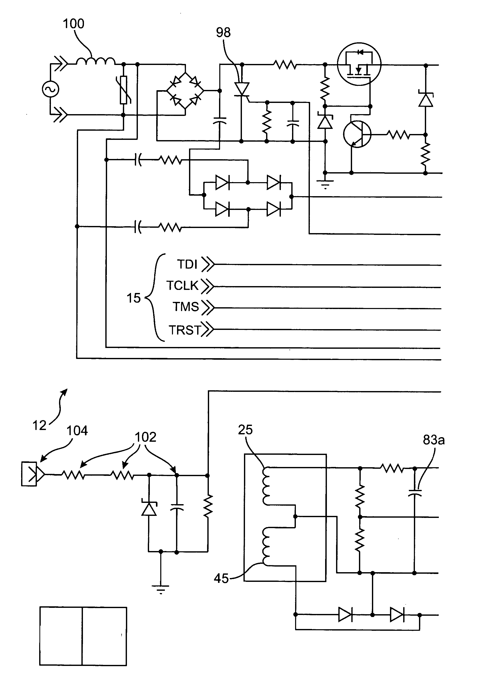
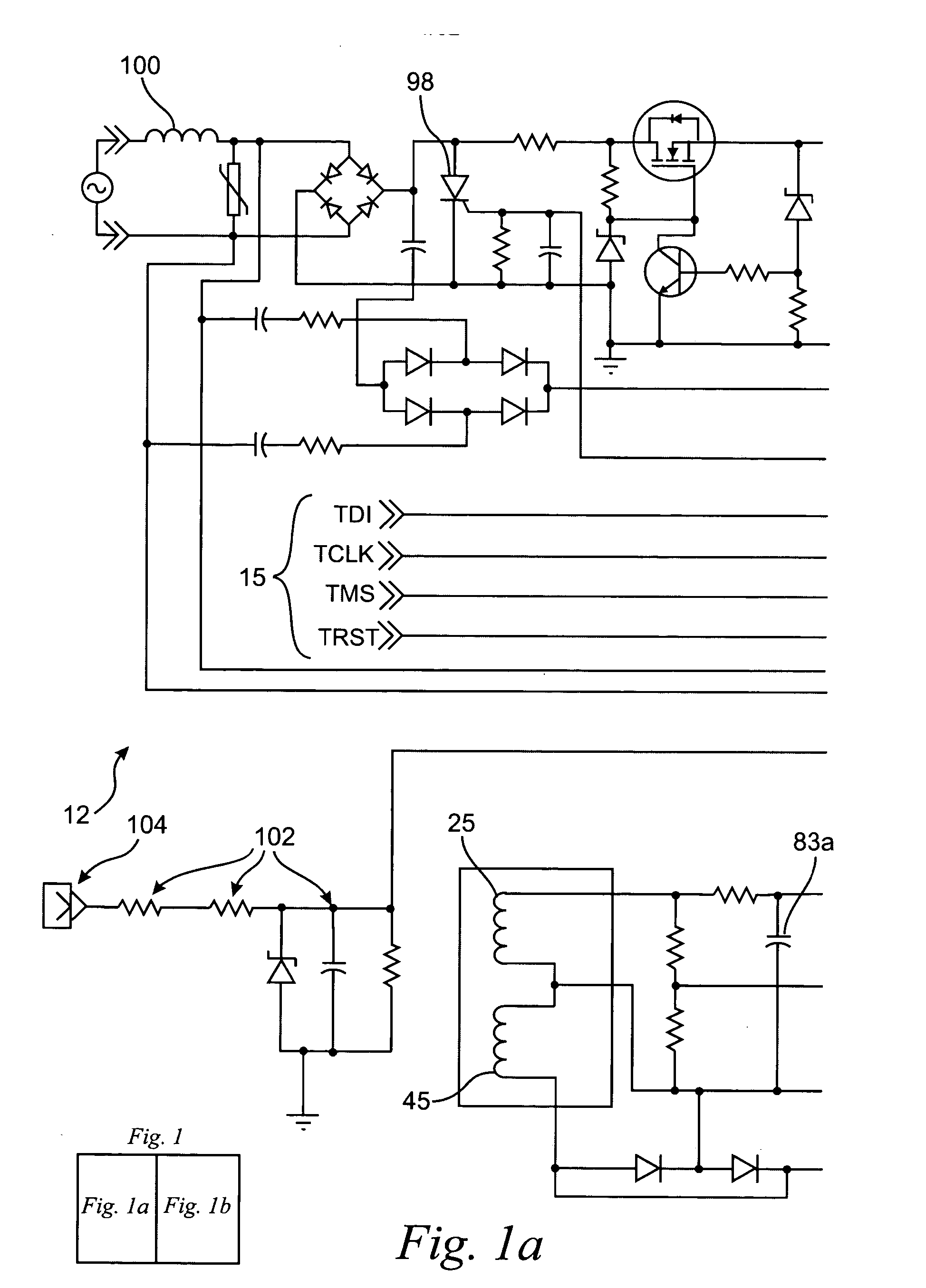
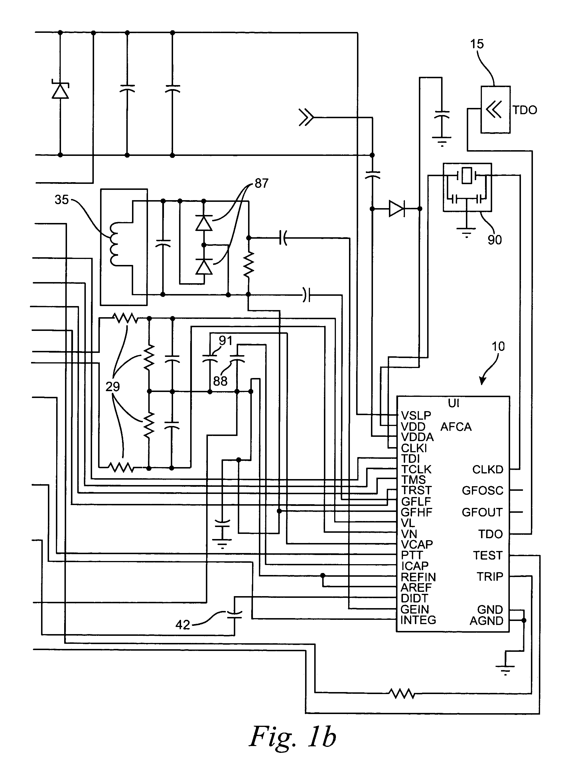
[0043] This invention pertains to the use of a system on chip solution for arc fault detection primarily for use in circuit breakers or electrical outlet receptacles, or other electrical devices, typically but not limited to the 15 or 20 ampere size. Referring to FIGS. 1a and 1b, this microchip 10, when incorporated on an electronic printed wiring board 12 with a minimum of external components, provides arc fault detection and tripping of the host wiring device.

[0044] The system on chip is an application specific integrated circuit which combines analog and digital signal processing on a single microchip. A block diagram is shown in FIG. 2.

[0045] The "system on chip" 10 monitors line voltage and current in the host device and analyzes them for the presence of an arc fault. If certain arc detection criteria are met as determined by an arcing algorithm embedded within the software of a microcontroller's 14 memory 18, the chip signals an external SCR98 causing it to disconnect the devi...


PUM


Abstract

A method and system for determining whether arcing is present in an electrical circuit includes sensing a change in an alternating current in the circuit and developing a corresponding input signal, analyzing the input signal to determine the presence of broadband noise in a predetermined range of frequencies, and producing a corresponding output signal, and processing the input signal and the output signal in a predetermined fashion to determine whether an arcing fault is present in the circuit. The processing includes determining a type of load connected to the electrical circuit, based at least in part upon the input signal and the output signal, and monitoring high frequency noise in a 20 KHz band for each 1 / 8 cycle of the alternating current.

Description

[0001] This is a continuation-in-part of pending U.S. patent application Ser. No. 10 / 107,621, filed Mar. 27, 2002, entitled "Arc Detection Using Load Recognition, Harmonic Content and Broadband Noise", which is a continuation-in-part of U.S. patent application Ser. No. 09 / 981,603, filed Oct. 17, 2001, entitled "Arc Fault Circuit Interrupter System".[0002] The present invention relates to the protection of electrical circuits and, more particularly, to the detection of electrical faults of the type known as arcing faults in an electrical circuit.[0003] The electrical systems in residential, commercial and industrial applications usually include a panelboard for receiving electrical power from a utility source. The power is then routed through protection devices to designated branch circuits supplying one or more loads. These overcurrent devices are typically circuit interrupters such as circuit breakers and fuses which are designed to interrupt the electrical current if the limits of...

Claims


Application Information

Patent Timeline
IPC IPC(8): H02H1/00H02H3/44
CPCH02H1/0015G01R31/14H02H3/44
Inventor WONG, KON B.SCOTT, GARY W.DVORAK, ROBERT F.
Owner SCHNEIDER ELECTRIC USA INC
Learn More