Densifier for simultaneous conditioning of two cryogenic liquids

a densifier and cryogenic liquid technology, applied in domestic cooling apparatus, container discharge methods, lighting and heating apparatus, etc., can solve the problems of reducing the take-off weight and payload capacity, reducing the requirements of pressurizing gas, and affecting the current apparatus and techniques for densifying cryogenic propellants

Inactive Publication Date: 2004-04-01
SIERRA LOBO
View PDF42 Cites 19 Cited by
  • Summary
  • Abstract
  • Description
  • Claims
  • Application Information

AI Technical Summary

Problems solved by technology

First, increased propellant density translates into smaller propellant tanks which result in lower take-off weight and larger payload capacities.
In addition, lower operating pressures for expendable launch vehicles result in lower pressurizing gas requirements.
Current apparatus and techniques for densifying cryogenic propellants suffer from a number of drawbacks, principal among which is that most require moving parts in a cryogenic refrigeration system.
According to this method a mechanical machine having moving parts (the compressor) must operate adjacent to or in contact with cryogenic materials likely to cause machine failure.
The test program was cancelled primarily due to failure of the compressor.
Testing of the X-33 oxygen densifier has shown the cold gas compression units to be highly unstable, un-repeatable, and unreliable during operation for long periods of time; i.e. the time required to load a launch vehicle.
In fact, one of the compressor stages of the X-33 oxygen densifier has failed causing destructive damage to the impeller and impeller housing.
A heat exchanger is used to warm the evacuated vapor prior to entering the vacuum pumps because the pumps cannot handle cold vapors.
This technique has been used effectively since the 1960's to make slush nitrogen and hydrogen, however it still requires moving parts and the input of mechanical energy at high cost.
However, they too require rotating machinery operating at cryogenic temperatures.
Indeed, history has shown that cryogenic Stirling refrigeration systems require periodic maintenance to replace the moving parts, contributing to down-time and increased operation cost.
The major disadvantages of the above densification methods are poor reliability and high operational and maintenance costs associated with rotating machinery and moving parts.
The use of uncertain, or unreliable densification technologies for propellant densification is very risky for companies and governments that operate aerospace launch vehicles.
This risk is unacceptable, especially when a launch vehicle must launch within a specified time window which may be as narrow as 10 minutes.
Such narrow launch windows make intolerable any substantial risk of delay due to propellant densification system failure.
A key disadvantage of evaporative cooling techniques is the generation of sub-atmospheric pressures inside hydrogen storage tanks.
This can lead to a potentially catastrophic situation in which air (oxygen) from the atmosphere is drawn into the hydrogen system through a leaky seal or a vent.

Method used


Image

  • Densifier for simultaneous conditioning of two cryogenic liquids
  • Densifier for simultaneous conditioning of two cryogenic liquids
  • Densifier for simultaneous conditioning of two cryogenic liquids

Examples


Embodiment Construction

[0023] As used herein, when a range such as 5 to 25 (or 5-25) is given, this means preferably at least 5, and separately independently, preferably not more than 25. Also as used herein, the porosity of a heat absorptive material used in a regenerator refers to the proportion of void volume over total volume of the regenerator. For example, porosity refers to the total void volume within the regenerator, taking into account both a) the porosity of the heat absorptive material itself, and b) the superficial void space within the regenerator that is not occupied by heat absorptive material packed or present therein. Unless otherwise specified, all components described herein are made from conventional materials in a conventional manner.

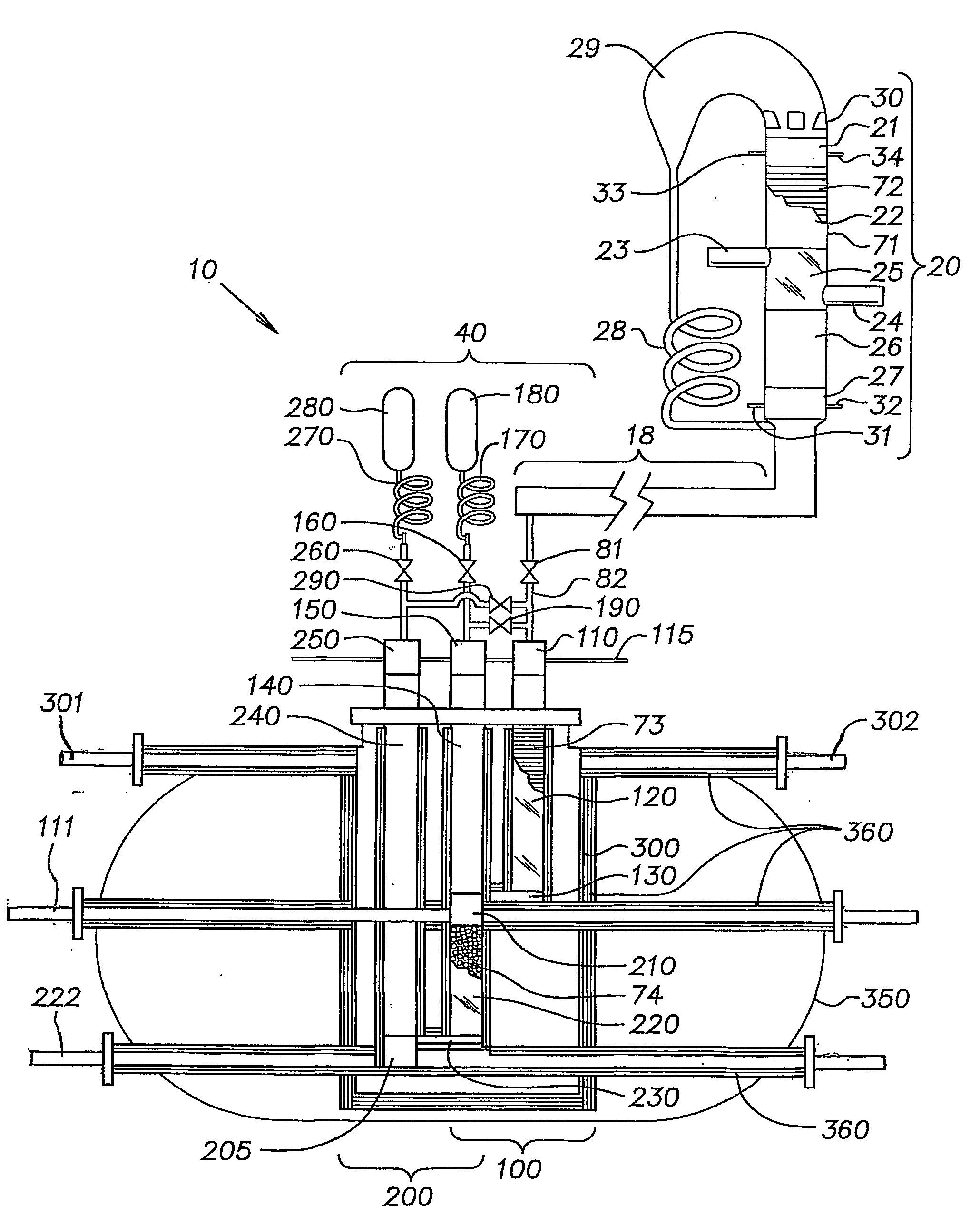
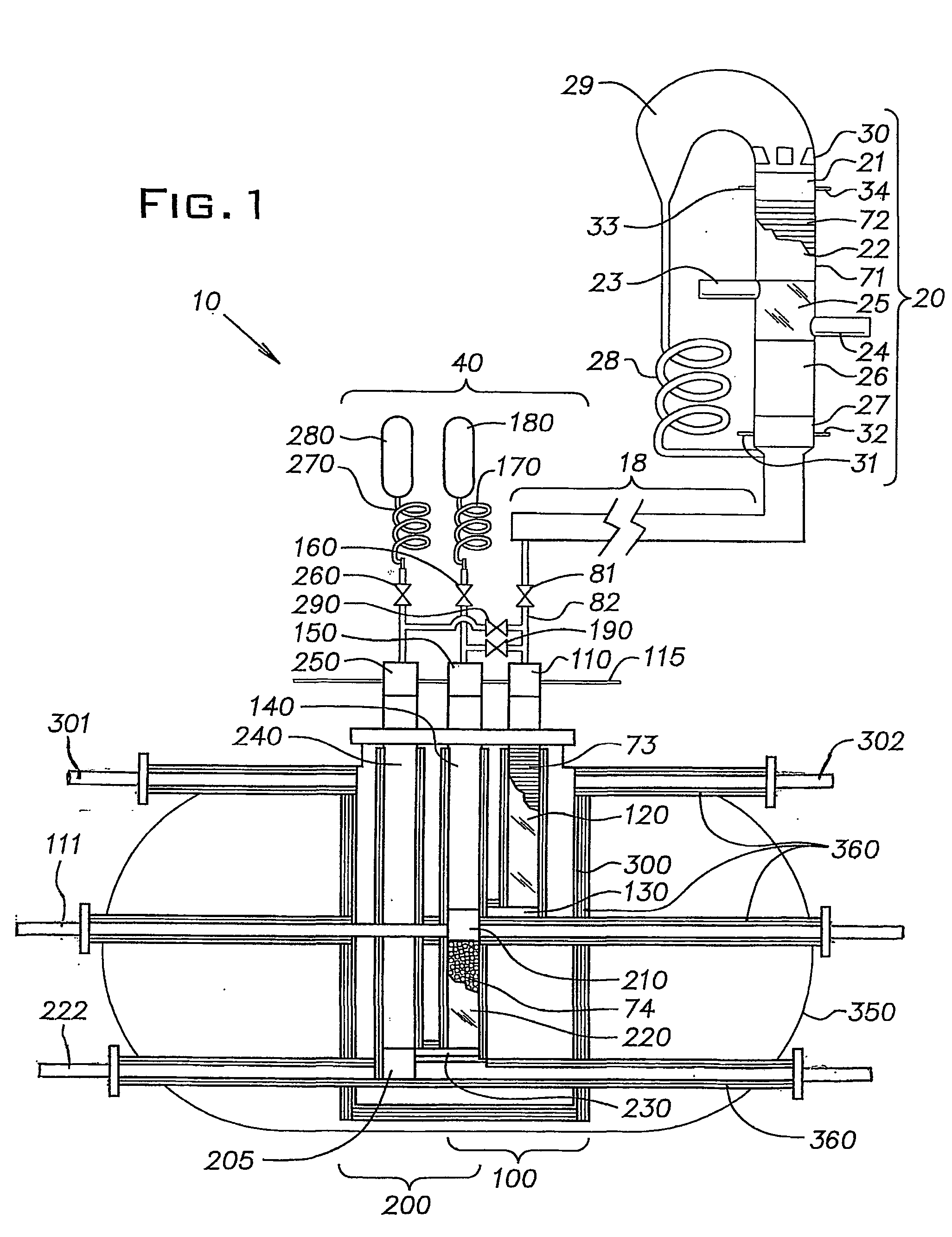
[0024] The invented densifier has three principal components; an oscillatory power source, a resonance tube 18, and a two-stage orifice pulse tube refrigerator (OPTR) 40. Referring to FIG. 1, a fully acoustic densifier 10 is shown having an acoustic heat...


PUM


Abstract

A densifier (10) for simultaneously densifying two cryogenic liquids at different temperatures is provided. The densifier (10) has a thermoacoustic heat engine (20), a resonance tube (18) and a two stage pulse tube refrigerator (40). The thermoacoustic heat engine (20) generates oscillatory acoustical power required to generate net refrigeration power in the two-stage pulse tube refrigerator (40). The first stage (100) densifies a first cryogenic liquid to a first cryogenic temperature, and the second stage (200) densifies a second cryogenic liquid to a second, lower cryogenic temperature. The thermoacoustic heat engine (20) converts thermal energy to the oscillatory acoustical power required to generate net refrigeration in the first (100) and second (200) stages of the pulse tube refrigerator (40). No mechanical energy input is required, and therefore the invented densifier (10) has no moving parts.

Description

[0001] 1. Field of the Invention[0002] The present invention relates to a densifier for the simultaneous conditioning and densification of two cryogenic liquids, and more particularly to a fully acoustic densifier for the simultaneous densification of two cryogenic propellants at different temperatures.[0003] 2. Description of Related Art[0004] Aerospace vehicles and spacecraft such as the space shuttle burn hydrogen fuel in the presence of oxygen for propulsion. To achieve maximum energy density and minimum storage volume, the hydrogen and oxygen propellants are stored onboard the spacecraft as cryogenic liquids. To achieve even greater energy density and lower volume, it is desirable to densify the cryogenic liquid propellants by subcooling or supercooling them below their normal boiling point temperatures.[0005] Liquid oxygen normally (at 1 ATM) boils at 90.15 K and liquid hydrogen at 20.25 K. At their boiling points, liquid oxygen and liquid hydrogen have densities of approximat...

Claims


Application Information

Patent Timeline
Patent Type & Authority Applications(United States)
IPC IPC(8): B64G1/40F02G1/043F17C5/04F17C13/00F25B9/14F25J1/00F25J1/02
CPCB64G1/402F02G1/043F02G2243/54F17C5/04F17C13/008F25B2309/1403F25D19/006F25B9/145F25B2309/003F25B2309/1411F25B2309/1423F25B2309/1424F25B9/10
Inventor HABERBUSCH, MARK S.
Owner SIERRA LOBO
Why Eureka
Try Eureka