Transformer and transformer unit having the same

Active Publication Date: 2004-06-17
PANASONIC CORP
View PDF5 Cites 13 Cited by
  • Summary
  • Abstract
  • Description
  • Claims
  • Application Information

AI Technical Summary

Problems solved by technology

Therefore, the printed board 71 itself becomes large-sized so that it is hard to meet the requirement for reducing the size of the high-frequency heating device.
Consequently, a cost is increased.
Thus, the size cannot be reduced.
Thus, it is possible to reduce a size without sacrificing the performance of the transformer and increasing a cost.
Therefore, the strand becomes fragile due to copper corrosion in solder bonding, and furthermore, becomes fragile due to a damage in welding for non-solder bondi

Method used


Image

  • Transformer and transformer unit having the same
  • Transformer and transformer unit having the same
  • Transformer and transformer unit having the same

Examples


Embodiment Construction

[0074] A preferred embodiment of a transformer and a transformer unit having the transformer according to the invention will be described below with reference to the drawings.

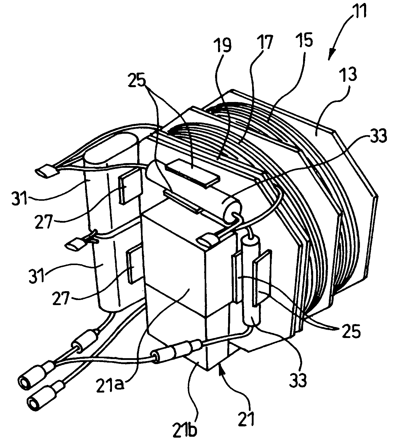
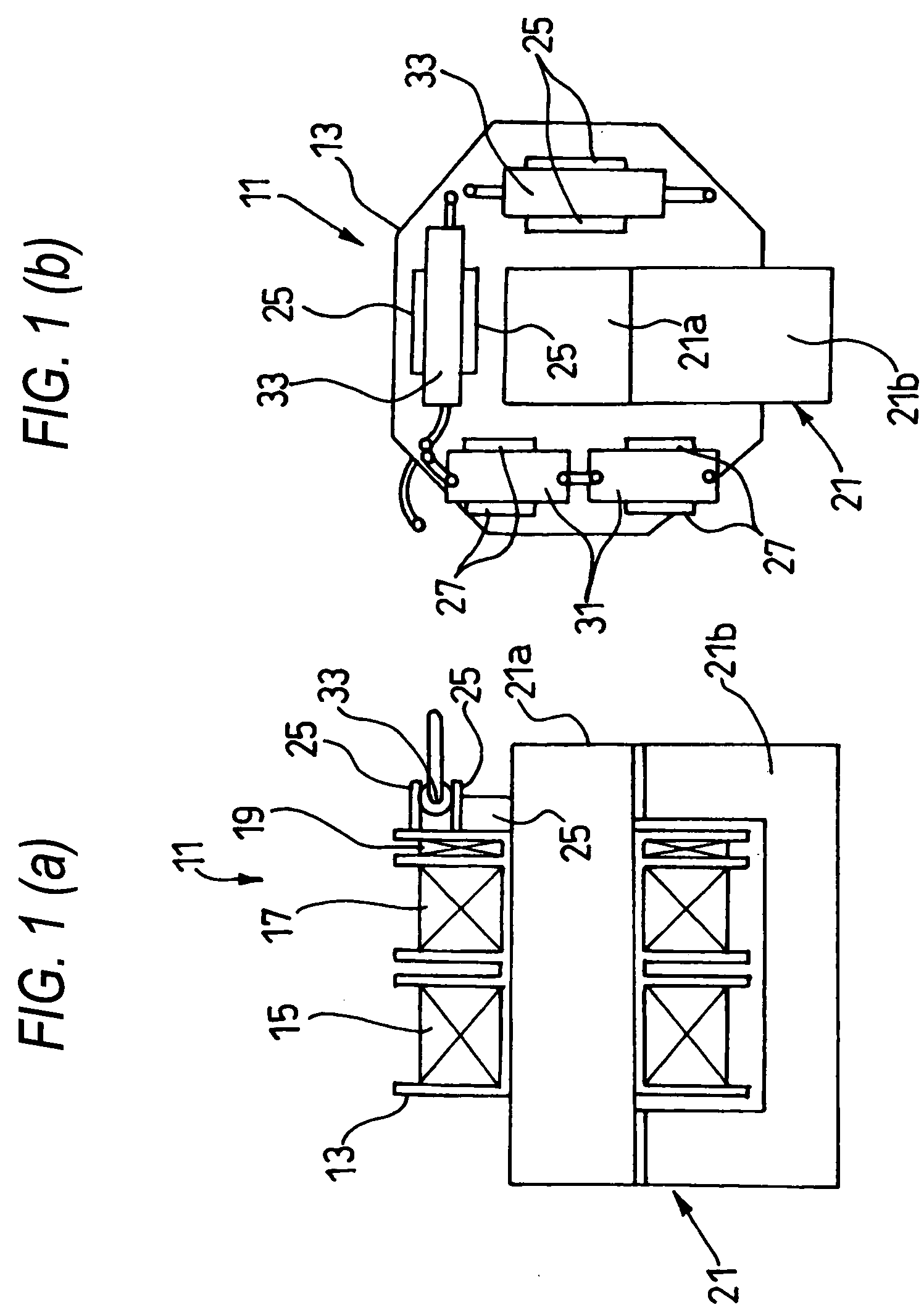
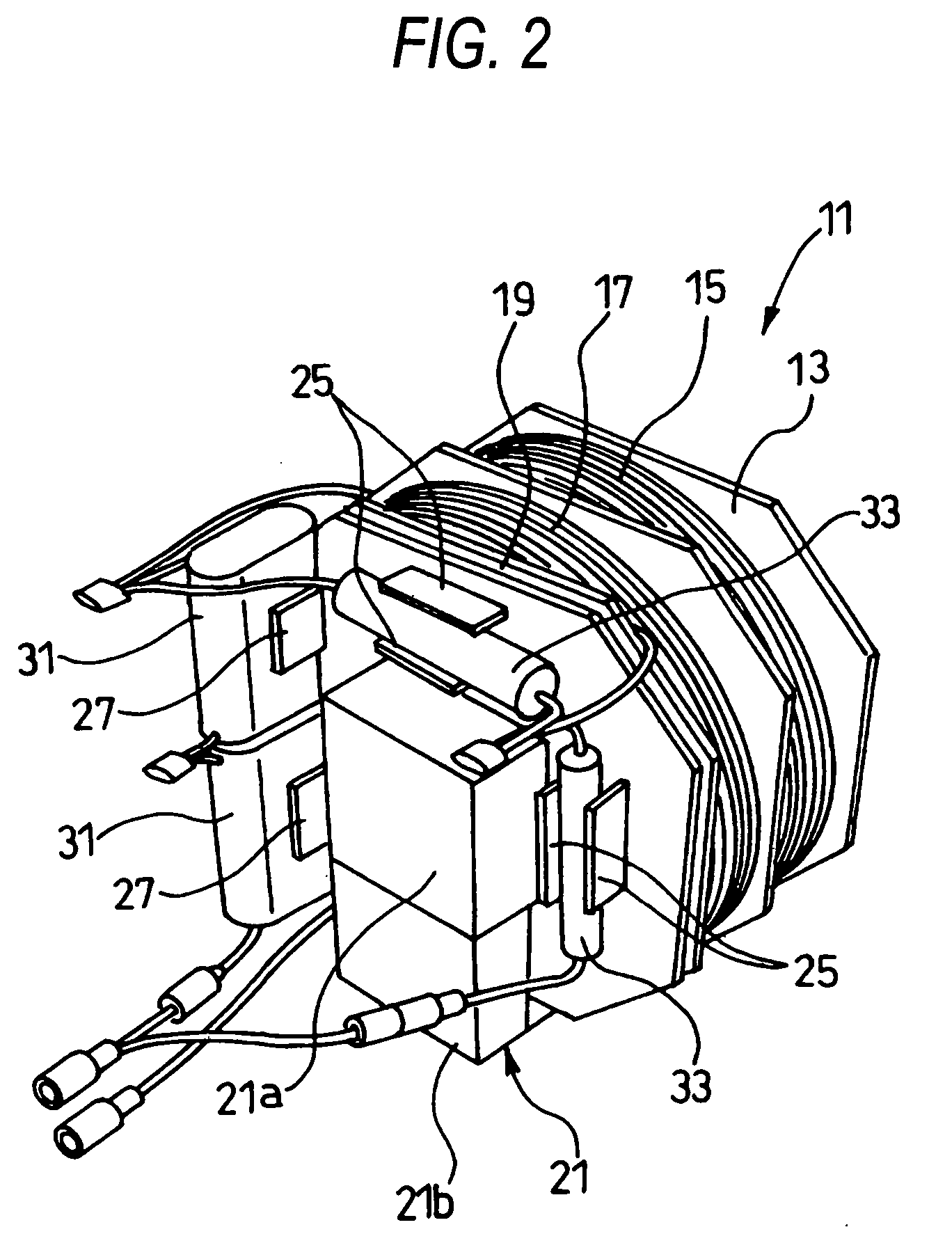
[0075] FIG. 1 is sectional and side views showing the transformer according to the invention, FIG. 2 is a perspective view showing the transformer, and FIG. 3 is a perspective view showing the transformer unit.

[0076] As shown in FIGS. 1 to 3, a transformer 11 to be mounted on the transformer unit according to the invention is mainly constituted by a bobbin 13 formed of a resin, a primary winding 15, a secondary winding 17 and a heater winding 19 which are wound around the bobbin 13, and a core 21.

[0077] The core 21 is constituted by an I-shaped core 21a having a rectangular section which is inserted through the center of the bobbin 13, and a U-shaped core 21b having a U shape seen from a side which is connected to both ends of the I-shaped core 21a, and the transformer 11 is mounted on a printed board 23 with t...


PUM


Abstract

It is an object to decrease an occupied space in a printed board to carry out space saving and to reduce the size of a unit without sacrificing the performance of a transformer and increasing a cost. A transformer 11 is constituted by a bobbin 13 having at least a primary winding 15 and a secondary winding 17 wound therearound and a core 21, and the side surface of the bobbin 13 is provided with a component holding section for holding high-voltage components such as a capacitor 31 and a diode 33 which constitute a voltage doubler rectifying circuit for rectifying a high voltage having a high frequency from the secondary winding 15.

Description

[0001] 1. Field of the Invention[0002] The present invention relates to a transformer to be used in an inverter system high-frequency heating device and a transformer unit having the transformer.[0003] 2. Description of the related Art[0004] The inverter system high-frequency heating device includes a transformer unit 73 mounting a transformer 72 on a printed board 71 as shown in FIG. 17.[0005] A circuit for the transformer unit 73 will be described with reference to FIG. 18.[0006] A commercial power source 74 is full-wave rectified by a rectifying circuit 75 such as a diode bridge and the power is converted into a high-frequency voltage by an inverter 76, and the high-frequency voltage is applied to a primary winding 77 of the transformer 72. Consequently, a high voltage having a high frequency of several kv is generated on a secondary winding 78 of the transformer 72. The high voltage having the high frequency is rectified by a voltage doubler rectifying circuit 81 comprising a ca...

Claims


Application Information

Patent Timeline
IPC IPC(8): H01F5/04H01F27/06H01F27/28H01F27/32H01F27/40H01F30/00H01F41/10H02M7/00H05B6/66H05K1/02H05K1/18
CPCH01F5/04H01F27/325H01F27/40H01F41/10H05K1/18H01F2038/003H02M7/003H05B6/662H05K1/0254H01F2027/065
Inventor SAKAI, SHINICHISATOU, KEIICHIYASUI, KENJISUENAGA, HARUOMORIKAWA, HISASHIODA, YOSHITAKASHIROKAWA, NOBUO
Owner PANASONIC CORP
Why Eureka
Try Eureka