Carbon annotate-based device and method for making carbon nanotube based device

a carbon nanotube and annotate technology, applied in the direction of discharge tube/lamp details, nanoinformatics, transportation and packaging, etc., can solve the problem that the idea of using external electric fields to direct the growth of carbon nanotubes is not suitable for building complicated structures

Active Publication Date: 2004-07-15
TSINGHUA UNIV +1
View PDF4 Cites 111 Cited by
  • Summary
  • Abstract
  • Description
  • Claims
  • Application Information

AI Technical Summary

Problems solved by technology

Furthermore, the idea of using external electric-fields to direct the carbon nanotube's growth is not suitable to build complicated structures wherein the carbon nanotubes bend in several directions.

Method used


Image

  • Carbon annotate-based device and method for making carbon nanotube based device
  • Carbon annotate-based device and method for making carbon nanotube based device
  • Carbon annotate-based device and method for making carbon nanotube based device

Examples


second embodiment

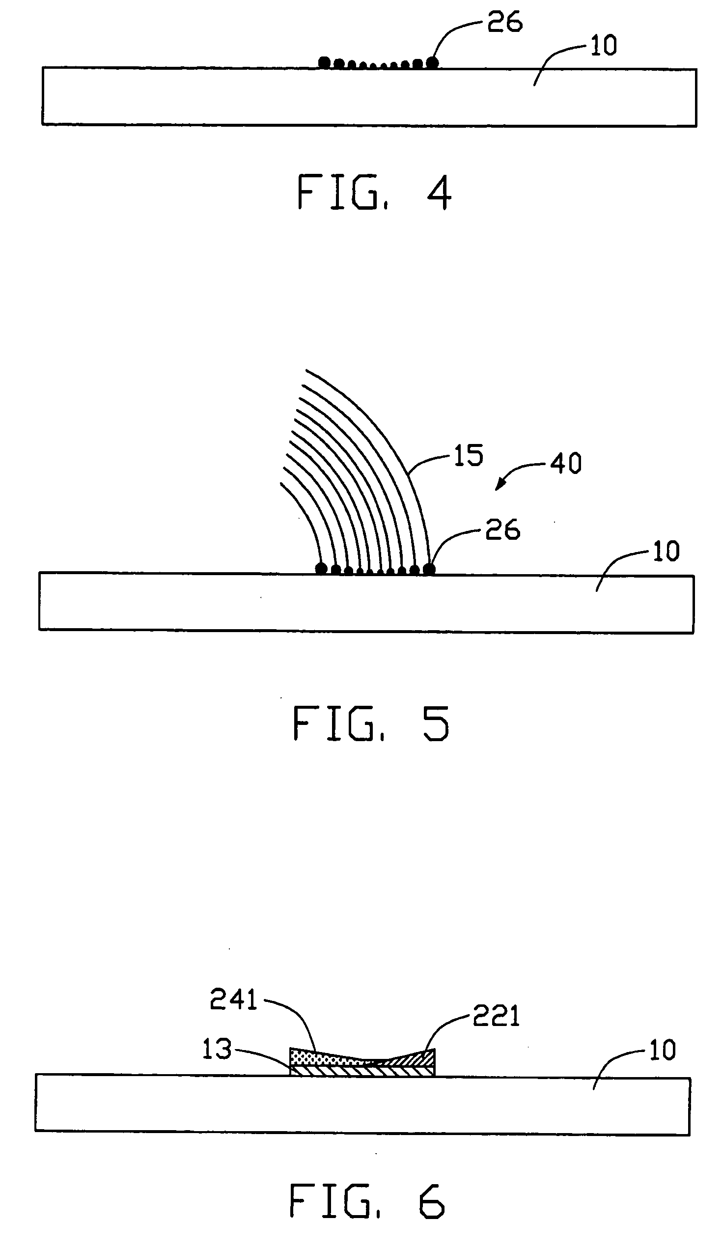
[0035] Referring to the FIG. 6, in the method, the thinner end of the first layer 221 partly underlies the thinner end of the second layer 241. It is allowable for some parts of the first layer 221 and the second layer 241 to overlap; the direction of bending of the aligned carbon nanotube array will not be changed.

third embodiment

[0036] Referring to the FIG. 7, in the method, the two catalyst-doped material layers 221, 241 completely overlap on the catalyst layer 13. FIG. 7 shows the first layer 221 as deposited first on the catalyst layer 13, and the second layer 241 as deposited second. The layers 221, 241 can be deposited by thermal evaporation. Alternatively, the two catalyst-doped material layers 221, 241 may be deposited at the same time. A total thickness of the catalyst-doped material layers 221, 241 and the catalyst layer 13 is essentially uniform the whole length of the catalyst layer 13.

[0037] Referring to the FIGS. 8 and 9, in the third embodiment, the catalyst layer 13 is oxidized and changed into nano-sized catalytic particles (not shown), in similar fashion to the preferred method described above. The treated substrate 10 is then put into a furnace (not shown), and the catalyst-doped material layers 221, 241 melt, forming uniform-sized, alloyed, nano-sized catalytic particles 28. A change in t...

fourth embodiment

[0039] Referring to FIG. 10, the method of the present invention is provided. Many evaporation sources 16 having different catalyst-doped materials are disposed at different positions in order to provide consecutive depositing of various catalyst-doped materials on the catalyst layer 13 by thermal evaporation. Respective speeds of carbon nanotube growth can be controlled by regulating deposition of the different catalyst-doped materials in different areas of the catalyst layer 13, so that a resulting array of aligned carbon nanotubes bends in a predetermined direction.

[0040] It will be apparent to those having ordinary skill in the field of the present invention that an order of depositing the catalyst-doped materials may be altered from that described above without effecting the reasultant annotate array 15. It will also be apparent to those having ordinary skill in the field of the present invention that if the time order rather than the position order of deposition of the catalys...


PUM

PropertyMeasurementUnit
thicknessaaaaaaaaaa
thicknessaaaaaaaaaa
temperatureaaaaaaaaaa

Abstract

A carbon nanotube-based device (40) includes a substrate (10), a number of alloyed, nano-sized catalytic particles (26) formed on the substrate, and an array of aligned carbon nanotubes (15) extending from the alloyed, nano-sized catalytic particles. The nanotube array bends in an arcuate configuation. A method for making the carbon nanotube-based device includes the steps of: providing a substrate; depositing a catalyst layer on the substrate; depositing two different layers of catalyst-doped materials on different areas of the catalyst layer for accelerating or decelerating the rate of synthesis of the aligned carbon nanotube array; annealing the catalyst and the catalyst-doped materials in an oxygen-containing gas at a low temperature; introducing a carbon source gas; and forming an array of aligned carbon nanotubes extending from the alloyed, nano-sized catalytic particles using a chemical vapor deposition method.

Description

[0001] 1. Field of the Invention[0002] The present invention relates to a carbon nanotube-based device and a method for making such a carbon nanotube-based device.[0003] 2. Description of Related Art[0004] Carbon nanotubes are very small tube-shaped structures having the composition of a graphite sheet rolled into a tube. Carbon nanotubes produced by arc discharge between graphite rods were first discovered and reported in an article by Sumio Iijima titled "Helical Microtubules of Graphitic Carbon" (Nature, Vol. 354, Nov. 7, 1991, pp. 56-58). Carbon nanotubes have very high electrical conductivity along a length thereof and are chemically stable, and have very small diameters (less than 100 nanometers) and large aspect ratios (length / diameter). Due to these and other properties, it has been suggested that carbon nanotubes can play an important role in fields such as microscopic electronics, materials science, biology and chemistry. Recently, a few electronic components based on a si...

Claims


Application Information

Patent Timeline
Patent Type & Authority Applications(United States)
IPC IPC(8): D01F9/127
CPCB82Y10/00Y10T428/30D01F9/127B82Y30/00
Inventor LIU, LIANGFAN, SHOUSHAN
Owner TSINGHUA UNIV
Why Eureka
Try Eureka