
Method for continous production of decorative facing slabs and a device for carrying out said method, decorative facing material

a production method and technology for decorative facings, applied in the direction of decorative arts, glass shaping apparatus, ornamental structures, etc., can solve the problems of low quality of firing slabs, warping and cracking, low quality of resulting slabs, etc., to reduce temperature differences, improve physico-mechanical, thermal and aesthetic properties, and expand the field of application

Inactive Publication Date: 2004-07-29
REZNIK VALENTIN JURIEVICH +4
View PDF3 Cites 5 Cited by
  • Summary
  • Abstract
  • Description
  • Claims
  • Application Information

AI Technical Summary

Benefits of technology

[0015] The technical problem solved by the invention consists in providing a method for continuous production of decorative facing slabs and a device for carrying out said method, which would eliminate the above-mentioned disadvantages of the methods and devices known at present, by reducing the temperature differences both in depth and over the surfaces of the slabs in the process of firing and thereafter, and also in providing a decorative facing material with improved physico-mechanical, thermal and aesthetic properties, hence enlarging the fields of its application and enhancing disigning capabilities of the decorative facing material.

Problems solved by technology

A disadvantage of the known method consists in low quality of the resulting slabs, and namely: warping and cracking caused by substantial temperature differences with depth and over the surfaces of slabs in the tunnel furnace and by drawing cold air into it.
Disadvantages of the known method for production of decorative facing slabs consist in low quality of firing the slabs because of a high cooling rate leading to large temperature differences both in depth and over the surfaces of slabs both in the process of firing (with residual stresses occuring in the material) and in the process of further cooling (with temporary stresses occuring therein).
Besides, a low cooling rate at an initial stage (prior to firing) leads to additional influence of high temperatures upon the casting moulds, thus causing their deformation and affecting quality of the slabs because of their greater variable thickness differences and flatness errors.
Disadvantages of the known device consist in substantial power intensity and considerable specific consumption of materials and low quality of products because of drawing cold air into it and deformation of casting moulds and roller conveyor caused by prolonged exposure to high temperatures.
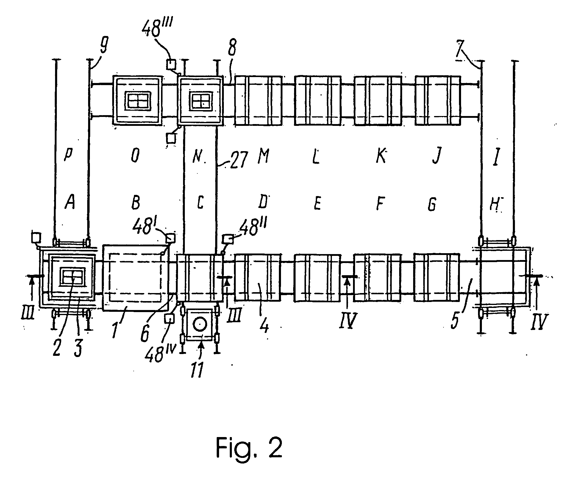
Disadvantages of the known device for production of decorative facing slabs consist in:
large temperature differences both in depth and over the surfaces of the slabs because of a high cooling rate when firing the slabs and after their firing as well as uncontrollable temperature differences because of drawing cold air in (if the covers get deformed), fringe effects and heating effect of the pallets on each other, hence impairing firing and reducing the percentage of usable products yielded; and
deformation of the pallets and covers because of mechanical and prolonged high-temperature exposures, hence reducing a service life of equipment and affecting quality of the slabs (increasing their variable thickness differences and flatness errors).
The known material has reduced mechanical properties and, in particular, high abradability.
Disadvantages of the known decorative facing material consisting of two unlike layers, with an upper, face layer of glass pelletizer, reside in structural discontinuity and burnt mirror face, resulting in a reduction in physico-mechanical and thermal properties.
Besides, a single mirror surface of the face layer, when lighted, gives rise to shines, thus affecting the aesthetic perception of the decorative facing material, and in case of using it to lay floor, leads to substantial slipping that makes such floor unsafe.

Method used


Image

  • Method for continous production of decorative facing slabs and a device for carrying out said method, decorative facing material
  • Method for continous production of decorative facing slabs and a device for carrying out said method, decorative facing material
  • Method for continous production of decorative facing slabs and a device for carrying out said method, decorative facing material

Examples


example

[0078] The moulds of 330.times.430 mm in size that are made of quartz ceramics, are first cleaned of dust, dirt and stuck particles and then smeared inside with kaoline slip and dried.

[0079] A layer of quartz sand 2 mm thick and then a layer of mixture of colour glass pelletizer and refractory filler 20 mm thick (to produce a finished slab of 12 mm in thickness) and wetted to 4% moisture content are filled into a mould thus dried on the bottom, and the mixture is rammed.

[0080] In order to produce decorative facing slabs of light blue colour, use is made of colour glass pelletizer with the pellets of 1.6 mm to 5 mm in size and having the following chemical composition (wt. %): SiO.sub.2--60.0; Na.sub.2O--16.8; CaO--5.6; Al.sub.2O.sub.5--5.8; P.sub.2O.sub.5--9.1; NaNO.sub.3--1.5; CuSO.sub.4--0.8; CuO--0.4.

[0081] Four such moulds with homogeneous mixture filled in are placed into a recess of a heat-insulated pallet. The pallet is then placed under an electrical bell furnace preheated t...

example no.1

Example No. 1

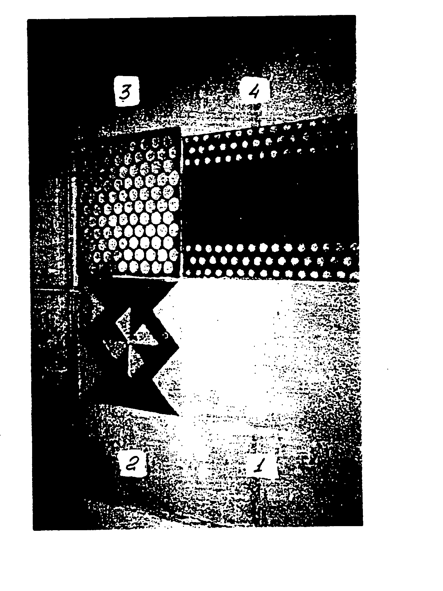
[0096] (FIG. 5, Ref. Nos. 2 and 4, Black Sections)

[0097] Preliminarily prepared colour glass pelletizer (chemical composition and coefficients of linear thermal expansion are given in Table No. 1) with pellet size of 1.6 mm to 5.0 mm and quartz sand (percentages in the mixture are indicated in Table No. 1) with particle size of 0.15 mm to 0.4 mm are loaded into tared vessels; a hopper-type container for glass pelletizer (capacity 150 kg) and a container for quartz sand (capacity 40 kg). The quantity of quartz sand by weight in the decorative facing material was 22.5 kg.

[0098] Preliminarily, the mixer, use has been made of SBR-200 concrete mixer, is supplied with a dosed quantity of glass pelletizer which is wetted to have a moisture content of up to 4 percent and then mixed for as long as 5 minutes (prior to turning on, the concrete mixer window is tightly closed).

[0099] Next, a measuring vessel is used to load quartz sand therein, followed by additional mixing for 10 m...

example no.2

Example No. 2

[0104] (FIG. 5, Ref. No. 1)

[0105] All the operations are carried out as in Example No. 1, but prior to placing the moulds into the recess of the heat-insulated pallet, the entire face of the homogeneous layer of the mixture of colour glass pelletizer and quartz sand is additionally coated with a uniform layer of quartz sand 1 mm to 3 mm thick. After baking, the excess of quartz sand is easily removed from the upper layer by a stiff brush. As a result, a rough surface layer is formed which contains 100 wt. % quartz sand and is fused into glass pelletizer.


PUM

PropertyMeasurementUnit
thermal resistanceaaaaaaaaaa
temperatureaaaaaaaaaa

Abstract

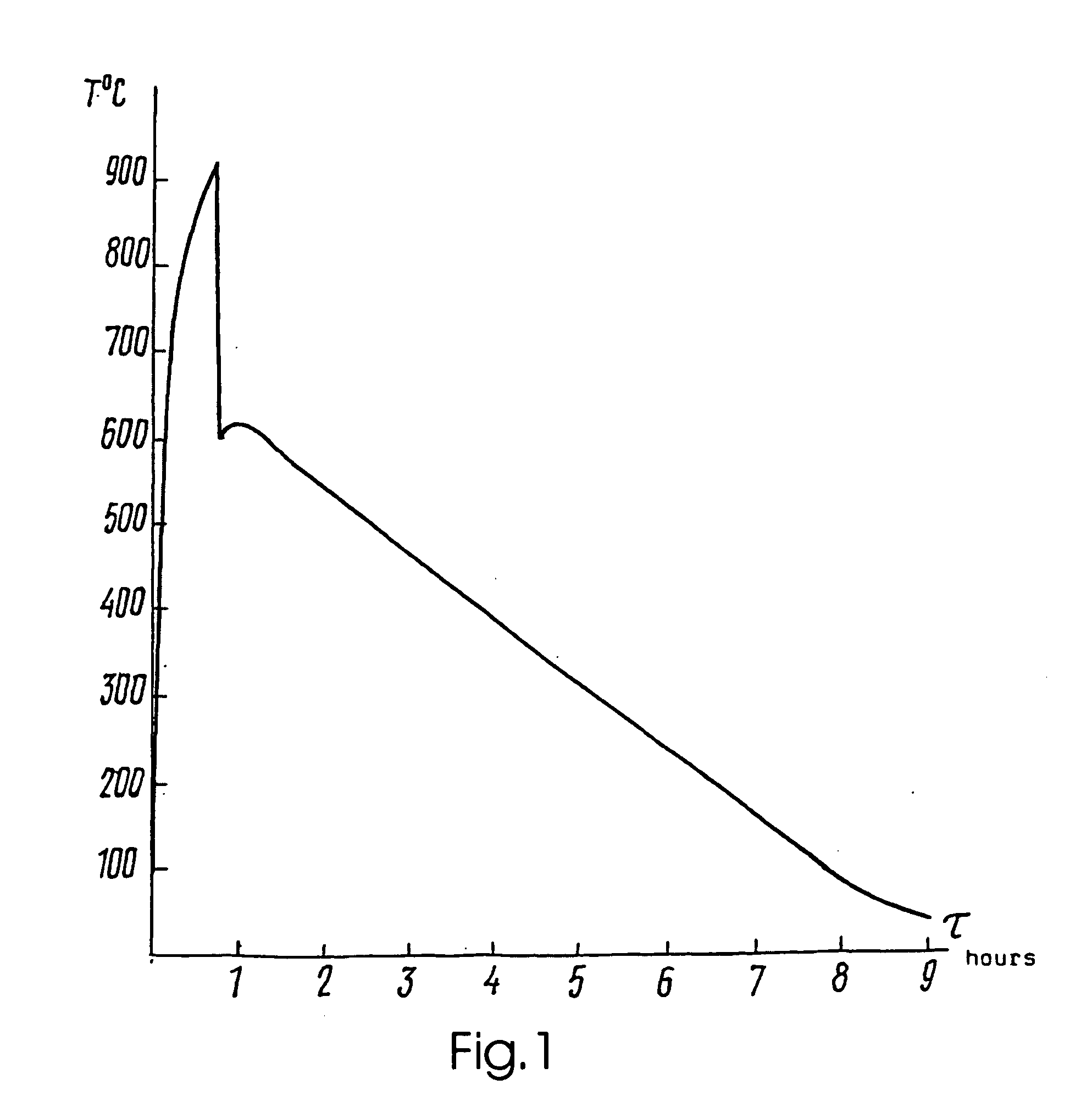
The invention relates to the production of decorative facing materials using a glass-pelletizer and refractory filler. The inventive method for a continuous production of decorative facing slabs consists in loading of basic materials into casting-moulds which are placed on an open heat-insulated palette, and in thermal treatment in a furnace at a temperature ranging from 900.degree. C. to 950.degree. C. After the thermal treatment, the palette with the moulds is taken out and conditioned at an ambient temperature during 80-90 sec accompanied by cooling the surface of the slabs to a temperature ranging from 600.degree. C. to 634.degree. C. Afterwards, the slabs are placed in a heat-insulated closed space having a thermal resistance of walls which makes it possible to cool the surface of the slab to a temperature ranging from 100.degree. C. to 140.degree. C. with an average cooling rate ranging from 0.016 to 0.020 degrees / sec.

Description

[0001] The invention relates to the production of decorative facing materials based on glass pelletizer and refractory filler and, in particular, to a method for continuous production of decorative facing slabs and a device for carrying out said method as well as to a decorative facing material.STATE OF THE ART[0002] A method is known to be used for continuous production of decorative facing slabs based on colour glass pelletizer and refractory filler, for instance, quartz sand, the method including laying basic materials layer by layer into a casting mould, followed by thermal treatment to fuse, bake and fire them in a tunnel furnace (USSR Inventor's Certificate No. 1546442, C1. C03B 31 / 00, publ. 1990).[0003] A disadvantage of the known method consists in low quality of the resulting slabs, and namely: warping and cracking caused by substantial temperature differences with depth and over the surfaces of slabs in the tunnel furnace and by drawing cold air into it.[0004] The closest ...

Claims


Application Information

Patent Timeline
Patent Type & Authority Applications(United States)
IPC IPC(8): B44C3/04C03B19/06C03B19/09C03B32/00C04B32/00
CPCB44C3/04C03B19/06C03B19/09C03B32/00Y10T428/315C04B32/005C04B14/22C04B14/30Y02P40/57
Inventor REZNIK, VALENTIN JURIEVICHAKHAPKIN, KONSTANTIN VIKTOROVICHGRISCHENKO, SERGEI EVGENIEVICHMELESHKO, VIKTOR MIKHAILOVICHSHITUEVA, IRINA VLADIMIROVNA
Owner REZNIK VALENTIN JURIEVICH
Learn More