Fuel Container
a technology of fuel containers and polyethylene, which is applied in the direction of transportation items, liquid transferring devices, synthetic resin layered products, etc., can solve the problems of insufficient suppression of gasoline permeation amount, easy penetration of stored liquid gasoline and/or vaporized gasoline through polyethylene walls into the atmosphere, etc., to achieve high crystallinity, increase melt stability of copolymer, and high barrier properties
- Summary
- Abstract
- Description
- Claims
- Application Information
AI Technical Summary
Benefits of technology
Problems solved by technology
Method used
Image
Examples
example 1
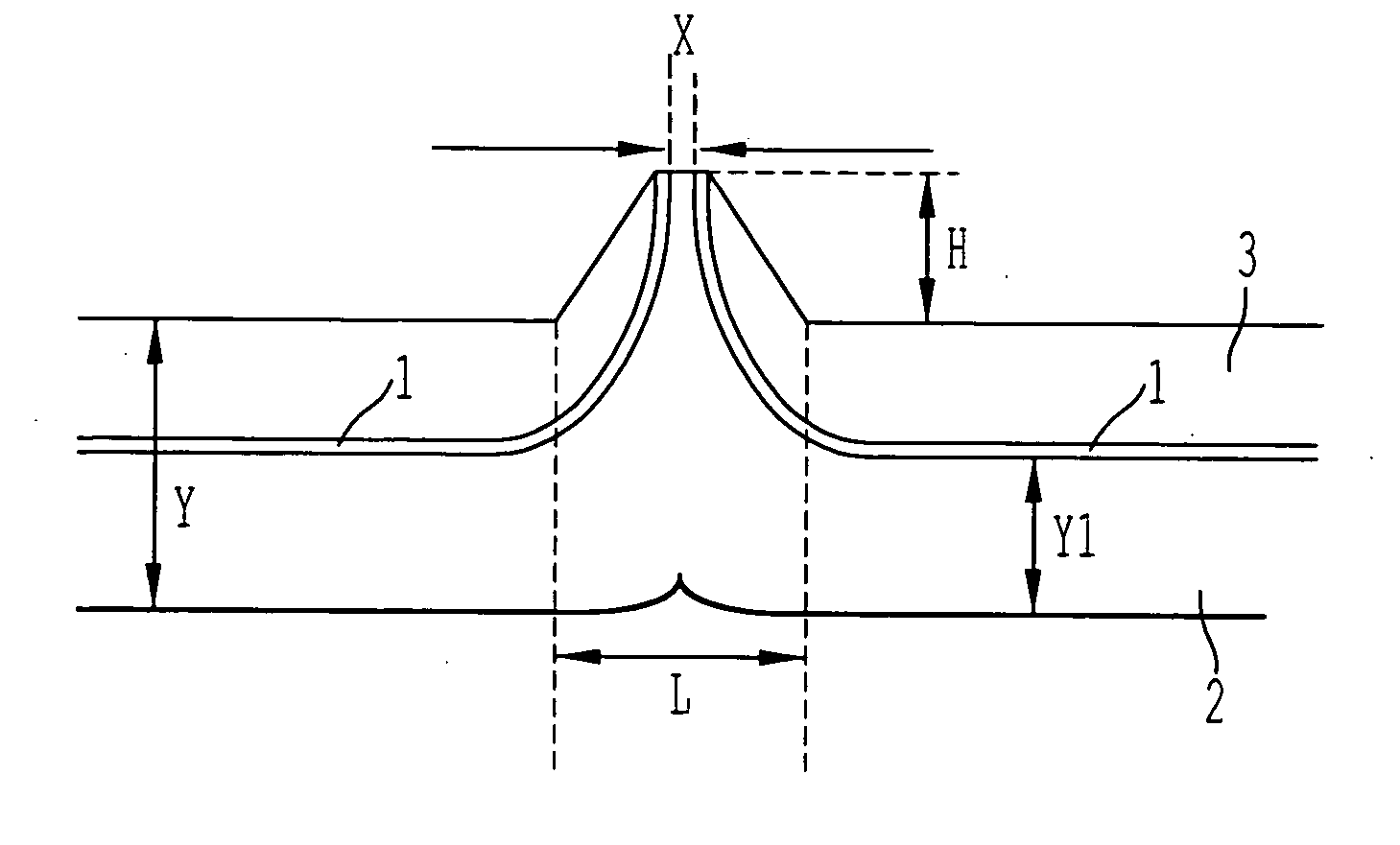
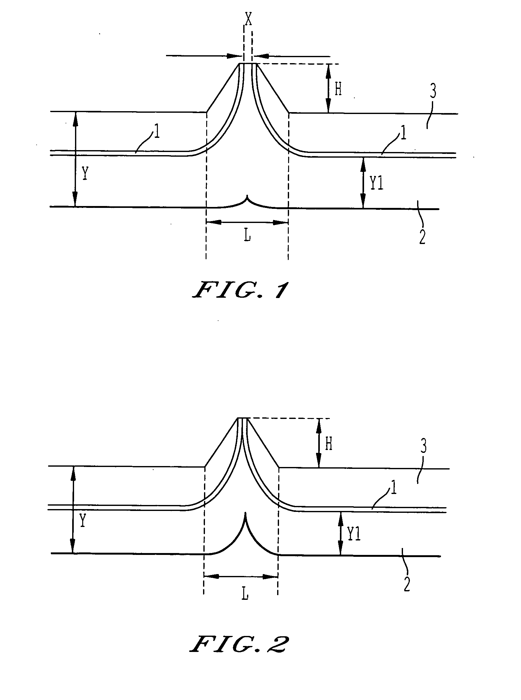
[0204] For the thermoplastic resin (B), the high-density polyethylene (HDPE) BA-46-055 (having a density of 0.970 g / cm.sup.3, and a MFR of 0.03 g / 10 min at 190.degree. C. and 2160 g) by Paxon was used; for the adhesive resin (D), ADMER GT-6A (having a MFR of 0.94 g / 10 min at 190.degree. C. and 2160 g) by Mitsui Chemicals, Inc. was used; and for the barrier resin (A), an ethylene-vinyl alcohol copolymer including 32 mol % of ethylene and having a degree of saponification of 99.5 mol %, and having a MFR of 1.3 / 10 min at 190.degree. C. and 2160 g was used. Using these resins, a fuel tank was obtained by blow-molding with a blow-molding machine TB-ST-6P by Suzuki Tetsukousho according to the following steps. (The molding in the following examples and comparative examples was performed with the same blow-molding machine.) A three-resin five-layered parison with the structure (inner layer) HDPE / Tie / Barrier / Tie / HDPE (outer layer) was extruded at 210.degree. C. ("HDPE" denotes an high-densi...
example 3
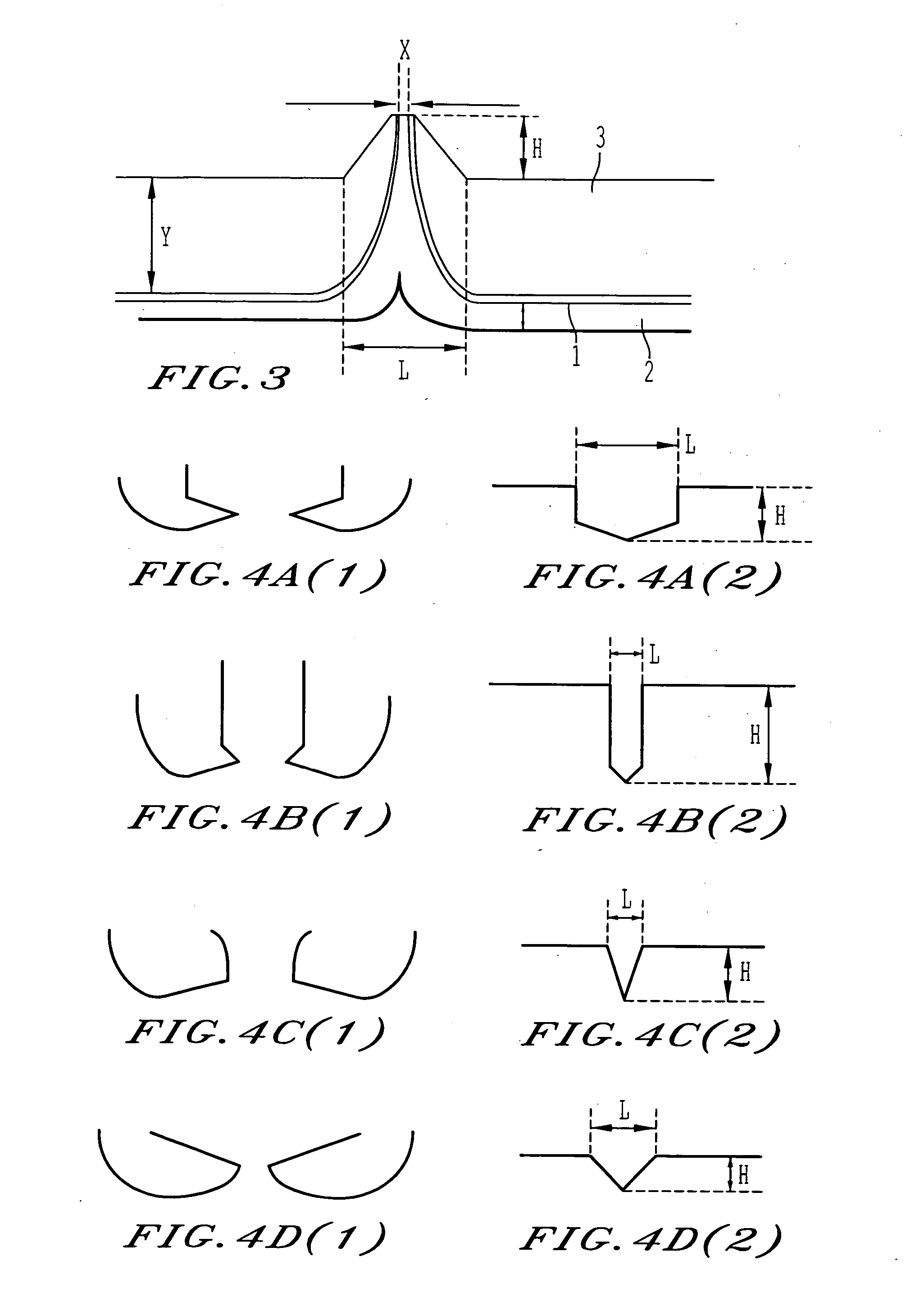
[0211] For the thermoplastic resin (B) the adhesive resin (D) and the barrier resin (A), the same resins as the ones in Example 1 were used. Moreover, as a recovered resin, a resin mixture obtained by crushing a tank made in accordance with Example 1 was used. Using these resins, a fuel tank was obtained by blow-molding according to the following steps. A four-resin six-layered parison with the structure (inner layer) HDPE / Tie / Barrier / Tie / recovered layer / HOPE (outer layer) was extruded at 210.degree. C. Then, molding was performed at a mold-cramping force of 3 tons with a mold having a pinch-off part forming section as shown in FIG. 4a. Blowing was performed in the mold at 15.degree. C., such that the ratio (X / Y) of the distance (X) between end portions of the barrier layer and the average thickness (Y) of the container body was 4 / 1000, the ratio (AIL) between height and length of the pinch-off part was 0.5, and the ratio (Y1 / Y) between the total thickness (Y1) of the layers of the ...
example 5
[0219] For the thermoplastic resin (B), the adhesive resin (D) and the barrier resin (A), the same resins as the ones in Example 1 were used. Moreover, as a recovered resin, a resin mixture obtained by crushing a tank made in accordance with Example 1 was used. Using these resins, a fuel tank was obtained by blow-molding according to the following steps. A four-resin seven-layered parison with the structure (inner layer) HDPE / recovered layer / Tie / Barrier / Tie / recovered layer / HDPE (outer layer) was extruded at 210.degree. C. Then, molding was performed at a mold-cramping force of 3 tons with a mold having a pinch-off part forming section as shown in FIG. 4a. Blowing was performed in the mold at 15.degree. C., such that the ratio (X / Y) of the distance (X) between end portions of the barrier layer and the average thickness (Y) of the container body was 411000, the ratio (H / L) between height and length of the pinch-off part was 0.5, and the ratio (Y1 / Y) between the total thickness (Y1) of...
PUM
| Property | Measurement | Unit |
|---|---|---|
| Angle | aaaaa | aaaaa |
| Angle | aaaaa | aaaaa |
| Mass | aaaaa | aaaaa |
Abstract
Description
Claims
Application Information
 - R&D
- Intellectual Property
- Life Sciences
- Materials
- Tech Scout
- Unparalleled Data Quality
- Higher Quality Content
- 60% Fewer Hallucinations
Browse by: Latest US Patents, China's latest patents, Technical Efficacy Thesaurus, Application Domain, Technology Topic, Popular Technical Reports.
© 2025 PatSnap. All rights reserved.Legal|Privacy policy|Modern Slavery Act Transparency Statement|Sitemap|About US| Contact US: help@patsnap.com


