CO removal catalyst, method of producing CO removal catalyst, hydrogen purifying device and fuel cell system

a technology of co removal catalyst and catalyst, which is applied in the direction of physical/chemical process catalyst, bulk chemical production, sustainable manufacturing/processing, etc., can solve the problems of consuming a large amount of hydrogen, and reducing the efficiency of the entire devi

Inactive Publication Date: 2004-09-16
PANASONIC CORP
View PDF24 Cites 4 Cited by
  • Summary
  • Abstract
  • Description
  • Claims
  • Application Information

AI Technical Summary

Benefits of technology

0143] The CO modifying portion 12 corresponds to the hydrogen purifying device of the invention. Further, the fuel cell portion 14 corresponds to the fuel cell of the invention. Moreover, the fuel cell system according to the present embodiment corresponds to the fuel cell system of the invention.
0144] The operation of the fuel cell system according to the present embodiment will be described hereinafter.
0145] Examples of the fuel to be supplied into the modifying portion 11 include natural gas, methanol, and gasoline. Examples of the modifying method include water vapor modification involving the addition of water vapor, and partial modification involving the addition of air. The invention will be described hereinafter with reference to the case where a natural gas is subjected to water vapor modification to obtain a modified gas.
0146] The natural gas which is a starting material is supplied into the modifying portion 11 from the starting material supplying portion 17. The water supplying portion 19 supplies water into the modifying portion 11 where it is evaporated and mixed with the starting material which is then brought into contact with the modification catalyst packed in the modifying portion 11. The catalyst is heated to a temperature of about 700.degree. C. so that the starting material is reacted with water vapor and converted to a modified gas mainly composed of hydrogen. The composition of the modified gas thus produced varies somewhat with the temperature of the modification catalyst. Referring to the average value excluding water vapor, the modified gas contains hydrogen in an amount of about 80% and carbon dioxide and carbon monoxide each in an amount of about 10%. The modified gas undergoes shift reaction at the CO modifying portion 12, which is provided down stream the modifying portion 11 , to reduce its CO concentration to a range of from about 0.3 to 1%. Subsequently, CO is reacted with oxygen in the air supplied from the purifying air supplying portion 20 to reduce the CO concentration of the modified gas to not higher than 10 ppm.
0147] The modified gas from which CO has thus been removed is then supplied into the fuel cell portion 14. At the fuel cell portion 14, hydrogen in the modified gas is then reacted with the air supplied from the cathode air supplying portion 21 to generate electricity.
0148] Since heat is generated as well during the generation of electricity, the fuel cell portion 14 is cooled with a cooling water (not shown) to keep the temperature of the fuel cell portion 14 constant. The hydrogen which has been left unreacted in the fuel cell portion 14 is then supplied as an off-gas into the heating portion 16 of heating the modifying portion 11. In the case where the off-gas is not sufficient to give the desired heat, a fuel is supplied from the heating fuel supplying portion 18.

Problems solved by technology

However, a solid polymer type fuel cell which operates at a temperature as low as not higher than 100.degree. C. is subject to poisoning of Pt catalyst used in the electrode of the fuel cell by CO contained in the modified gas.
When the Pt catalyst is poisoned, the reaction of hydrogen is inhibited, causing remarkable drop of the electricity-generation efficiency of the fuel cell.
When CO concentration is high, the amount of oxygen to be added increases, causing the rise of the consumed amount of hydrogen and hence causing a drastic drop of the efficiency of the entire device.
Moreover, since the CO modification catalyst which has once been activated can be reoxidized and deteriorated when mixed with oxygen during the suspension of the device or other occasions, some countermeasures such as antioxidation treatment are needed.
Further, since the low temperature CO modification catalyst has a low heat resistance and thus cannot be rapidly heated during the starting of the device, some countermeasures involving gradual heating or the like are needed.
However, CO modification reaction is an equilibrium reaction that can difficultly proceed toward the reduction of CO concentration at high temperatures.
Thus, when the high temperature CO modification catalyst, which performs only at high temperatures, is used, CO concentration can be difficultly reduced to not higher than 1%.
However, the aforementioned related art catalysts are disadvantageous in that the additive (alkali, alkaline earth, transition metal and rare earth elements) cannot be supported on the molded alumina, zirconia or titania (catalyst carrier) up to the interior thereof and only the noble metal supported on the outer part of the catalyst carrier in which the additive is present can perform.
Further, the noble metal supported on the portion of the carrier such as alumina, zirconia and titania in which the additive is not present not only is wasteful but also can cause methanization reaction which is a side reaction.
In the case where Pt is supported on ceria, ceria reacts with carbon dioxide or water in the modified gas to produce carbonates which then cover the surface of Pt, causing the deterioration of the catalyst activity.
Therefore, there is a problem that CO removal catalysts for use in fuel cell electricity generation leave something to be desired in properties.

Method used


Image

  • CO removal catalyst, method of producing CO removal catalyst, hydrogen purifying device and fuel cell system
  • CO removal catalyst, method of producing CO removal catalyst, hydrogen purifying device and fuel cell system
  • CO removal catalyst, method of producing CO removal catalyst, hydrogen purifying device and fuel cell system

Examples


embodiment 1

[0100] (Embodiment 1)

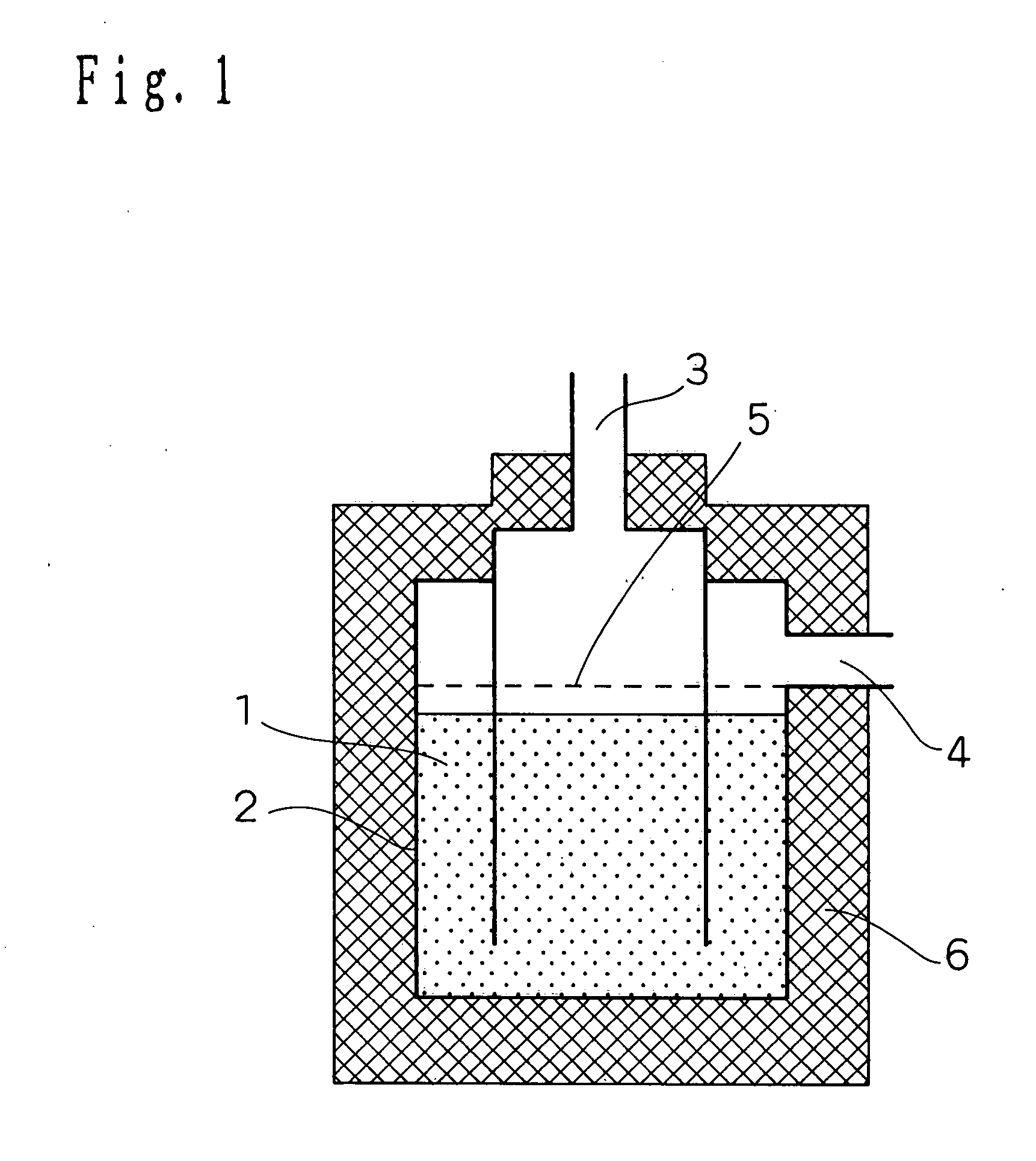
[0101] Firstly, the configuration of a hydrogen purifying device according to the present embodiment of implementation of the invention will be described in connection with FIG. 1. FIG. 1 is a schematic longitudinal sectional view illustrating the configuration of a hydrogen purifying device according to an embodiment 1 of implementation of the invention.

[0102] In FIG. 1, the reference numeral 1 indicates a CO removal catalyst (hereinafter simply referred to as "catalyst") which is provided inside a reactor 2. The reference numeral 3 indicates a modified gas inlet through which a modified gas is introduced. The modified gas which has been reacted is then discharged from a modified gas outlet 4.

[0103] Provided upstream the catalyst 1 is a diffuser plate 5 so that the modified gas can flow uniformly. In order to keep the reactor at a constant temperature, the periphery of the reactor is covered by an insulating material 6 made of ceramic wool at necessary areas.

[0...

embodiment 2

[0138] (Embodiment 2)

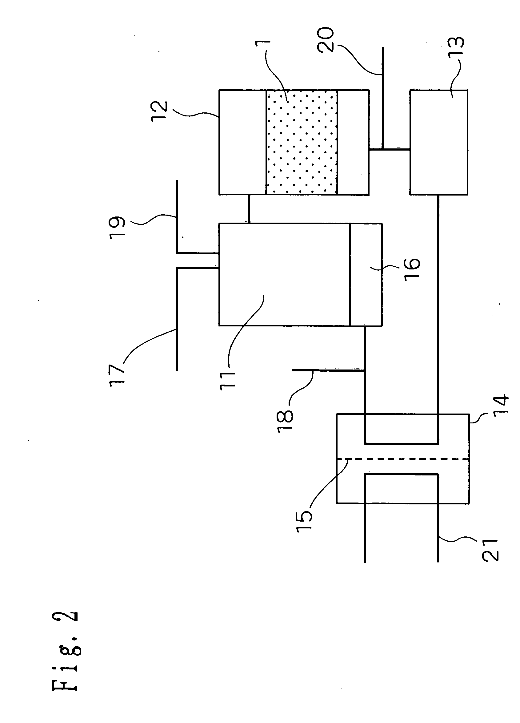
[0139] An embodiment 2 of implementation of the invention will be described hereinafter. FIG. 2 is a schematic diagram illustrating the structure of a fuel cell system according to the embodiment 2 of implementation of the invention. As shown in FIG. 2, the hydrogen purifying device according to the embodiment 1 of implementation of the invention is incorporated in the fuel cell system as CO modifying portion 12.

[0140] In FIG. 2, the reference numeral 11 indicates a modifying portion, the reference numeral 12 indicates a CO modifying portion corresponding to the hydrogen purifying device of the invention, the reference numeral 13 indicates a CO purifying portion, the reference numeral 14 indicates a fuel cell portion, and the reference numeral 15 indicates a protonically-conductive solid polymer electrolyte membrane.

[0141] There are provided a heating portion 16 of heating the modifying portion, a starting material supplying portion 17 of supplying a starting ma...

example

Example 1

[0151] Cerium and zirconium nitrate were each dissolved in purified water. The two aqueous solutions were then mixed at a ratio of 1:1 by weight as calculated in terms of CeO.sub.2 and ZrO.sub.2. Subsequently, the mixture was subjected to ordinary coprecipitation to prepare a precipitate which was then calcined at 500.degree. C. in the air atmosphere to obtain a ceria-zirconia composite oxide powder. The ceria-zirconia composite oxide powder thus obtained was then measured for BET specific surface area by nitrogen adsorption method, which is normally conducted. The result was 105 m.sup.2 per gram.

[0152] The powder was then subjected to structural analysis by powder X-ray diffractometry. No diffraction line attributed to single phase of ceria and zirconia was observed. It was thus confirmed that a uniform solid solution had been formed.

[0153] To the ceria-zirconia composite oxide thus obtained were then added a zirconia binder and a small amount of purified water such that t...


PUM

PropertyMeasurementUnit
particle diameteraaaaaaaaaa

Abstract

A CO removal catalyst of inducing CO shift reaction for allowing water and carbon monoxide to react to produce hydrogen and carbon dioxide, comprising a catalyst carrier having a cerium-zirconium composite oxide and a zirconium oxide and a predetermined noble metal supported on the catalyst carrier, wherein the average particle diameter of the particulate cerium-zirconium composite oxide is greater than the average particle diameter of the particulate zirconium oxide, the average particle diameter of the particulate zirconium oxide is greater than the average particle diameter of the predetermined particulate noble metal and the predetermined noble metal is supported on the catalyst carrier more in the outer part thereof.

Description

[0001] 1. Field of the Invention[0002] The present invention relates to a CO removal catalyst of purifying a modified gas mainly composed of hydrogen containing carbon monoxide (hereinafter referred to as "CO") to provide a high purity hydrogen gas, a method of producing a CO removal catalyst, a hydrogen purifying device and a fuel cell system.[0003] 2. Related Art of the Invention[0004] As a hydrogen source for fuel cell there is used a modified gas obtained by the modification of hydrocarbon, alcohol, ether, etc. However, a solid polymer type fuel cell which operates at a temperature as low as not higher than 100.degree. C. is subject to poisoning of Pt catalyst used in the electrode of the fuel cell by CO contained in the modified gas. When the Pt catalyst is poisoned, the reaction of hydrogen is inhibited, causing remarkable drop of the electricity-generation efficiency of the fuel cell. It is therefore necessary that CO be removed to a concentration of not higher than 100 ppm, ...

Claims


Application Information

Patent Timeline
Patent Type & Authority Applications(United States)
IPC IPC(8): B01J21/06B01J23/10B01J23/63B01J35/10B01J37/00B01J37/03C01B3/16
CPCB01J21/066Y02E60/50B01J23/63B01J35/0073B01J35/1038B01J37/0009B01J37/03C01B3/16C01B2203/0233C01B2203/0283C01B2203/044C01B2203/047C01B2203/066C01B2203/1017C01B2203/1052C01B2203/1064C01B2203/107C01B2203/1082C01B2203/1223C01B2203/1241C01B2203/1247H01M8/0668B01J23/10Y02P20/52Y02P70/50
Inventor TAGUCHI, KIYOSHIUKAI, KUNIHIROWAKITA, HIDENOBUFUJIHARA, SEIJI
Owner PANASONIC CORP
Why Eureka
Try Eureka