[0020] Once the working space is established, the anastomotic hole may be formed, conveniently using a conventional
cutting die. Optionally, the
cutting die can be modified in some way to accommodate presence of the
catheter extending outwardly through the anastomotic hole. The
catheter must, of course, remain in place so that the physician can continue to pull proximally on the
catheter in order to maintain the desired sealing and isolation of the working space. Thus, the anastomotic hole will have to be formed in such a way as to avoid interference from the catheter. One way of achieving such non-interference is to provide a channel in the side of an otherwise conventional anastomotic hole punch in order to accommodate the presence of the catheter.
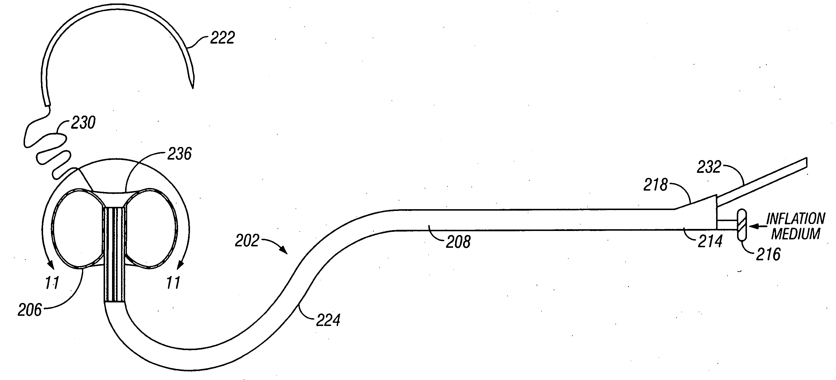
[0022] In an alternative protocol according to the present invention, the inflatable barrier may be positioned through a first or "access" penetration in the blood vessel wall and into the blood vessel lumen. The barrier is then advanced axially through the blood vessel lumen away from the first penetration. Usually, the second penetration is formed at the location of the working space, e.g. the anastomotic site, and a tether passed through the second penetration. The tether is attached to the inflatable barrier through the second penetration, and thus pulling on the tether will draw the inflatable barrier against the inner surface of the blood vessel at the working site. Optionally, a needle will be attached to a free or distal end of the tether so that the needle can form both the access penetration and the
needle penetration at the anastomotic site. Usually, the needle will be curved with a
radius that provides a desired spacing between the access penetration and the anastomotic site, typically from 1 cm to 10 cm, i.e., a
radius of curvature from 0.5 cm to 5 cm. The
balloon is inflated and the barrier is further drawn against the
arterial wall at the working site to the desired tension by pulling on the tether. Presence of the tether, which may be a
single filament or length of suture, is advantageous in that it presents little interference to formation of the anastomotic hole and subsequent suturing of the graft to the hole. Moreover, both the inflatable barrier and the tether may be withdrawn so that they pass outwardly through the access penetration, thus allowing the
anastomosis to be substantially completed before deflation of the inflatable barrier. The tether (with the needle being clipped off) which remains within the newly anastomosed site can be readily withdrawn inward without disturbing the
anastomosis.
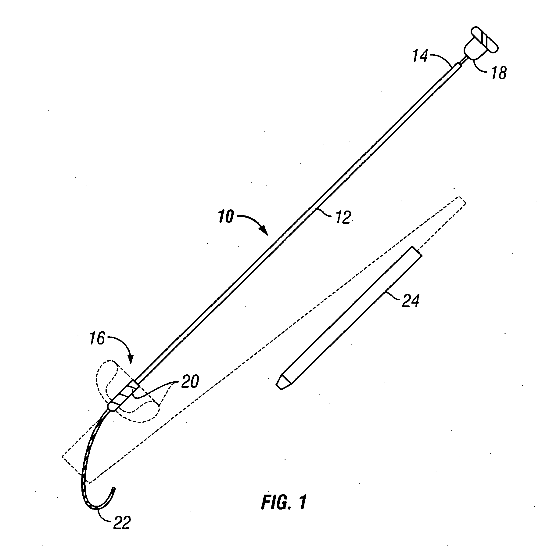
[0023] In a particular embodiment of the alternative protocol, the inflatable barrier is deployed by first passing a curved needle in through the access penetration and then outward through the second penetration in the blood vessel wall. The second penetration will be the anastomotic site. The needle is attached to the tether which is used to draw and position the inflatable barrier at the target anastomotic site. Usually, the inflatable barrier will be mounted at the end of a catheter, and at least a
distal portion of the catheter will be curved to facilitate locating the recessible surface of the barrier back against the inner wall of the blood vessel or other body lumen. More preferably, the curvature of the catheter will be "similar or congruent" with the curvature of the curved needle so that positioning of the inflatable barrier at the anastomotic site will "automatically" occur at the site of the anastomotic penetration made by the needle. By "similar" it is meant that the shape will be generally the same. By "congruent" it is meant that the curvature will be identical although the
arc length may differ. That is, the curvature of the needle will naturally locate the anastomotic penetration at a distance which is determined by the curved geometry of the needle. Since the catheter has the same curved geometry, it will tend to place the inflatable barrier directly at the anastomotic site. Precise alignment, of course, will be achieved with the tether which draws the inflatable barrier directly adjacent to the anastomotic site. In some embodiments, it may be preferable to provide needles, catheters, or both, which are malleable so that the degree of curvature can be modified by the operator immediately prior to use depending on patient
anatomy.
[0025] As with the first protocol, after the anastomotic hole is formed, the distal end of the graft vessel will be sutured or otherwise attached to the anastomotic hole while the tether remains in place between the newly placed graft vessel in the hole. As described above, however, the tether will then be withdrawn outwardly through the first penetration (not the anastomotic hole) in order to lessen interference with the anastomosis which has just been created.
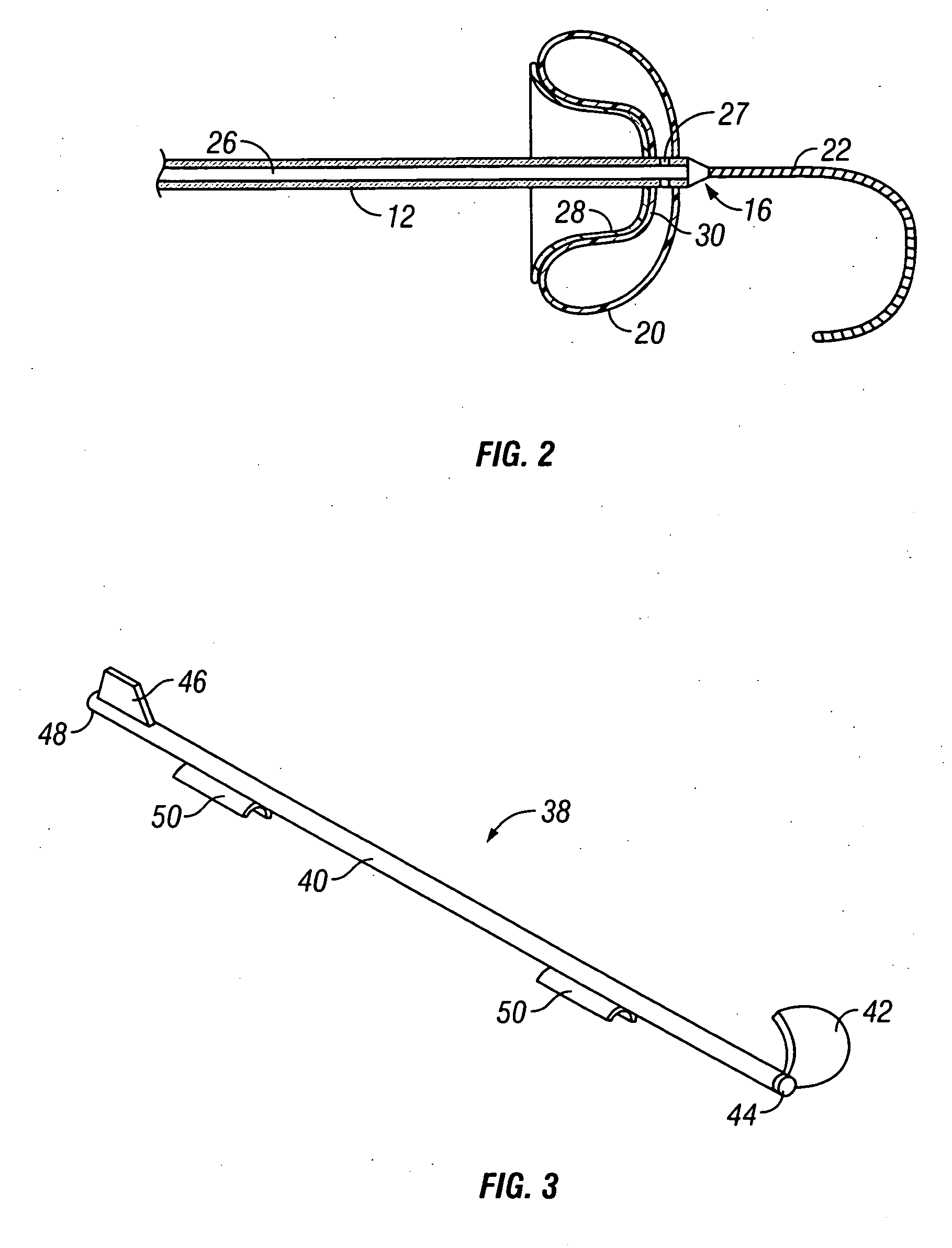
[0029] The means for introducing can take a variety of forms, but will usually comprise a catheter having a proximal end, a distal end, and an inflation lumen therethrough. The inflatable barrier is attached at or near the distal end of the shaft, and the recessible surface of the barrier may be disposed in either a proximal direction (so that the barrier may be deployed by pulling backwardly on the shaft to engage the surface against the blood vessel wall) or distally (so that the recessible surface may be deployed by advancing the shaft forwardly). The catheter itself may be straight, which is particularly useful in those embodiments where the barriers be deployed at a proximal direction. In some instances, at least a portion of the straight shafts will be formed so that they yield to axial tension so that the shaft can stretch as it is being deployed. Alternatively, when the inflatable barrier is to be deployed with the recessible surface disposed distally, the shaft will usually be curved so that the barrier can be engaged against the inner wall of the blood vessel by pushing the shaft forwardly and upwardly against the desired location, where the shaft is introduced through a penetration spaced-apart from the desired location. Optionally, in at least the straight shaft embodiments, the apparatus may further comprise a guidewire extending distally from the distal tip of the shaft. The guidewire is advantageous because it allows for the advancement of the catheter in a blind fashion with minimal trauma to the luminal surface of the
arterial wall opposite the penetration site.

