
Hydrogen generator and fuel cell system

a fuel cell and hydrogen generator technology, applied in electrochemical generators, sustainable manufacturing/processing, separation processes, etc., can solve the problems of significant reducing the power generation efficiency of the fuel cell, difficult to progress oxidization reaction, and poisoned platinum (pt) based catalyst used as an electrode of the fuel cell

Inactive Publication Date: 2004-12-02
PANASONIC CORP
View PDF3 Cites 15 Cited by
  • Summary
  • Abstract
  • Description
  • Claims
  • Application Information

AI Technical Summary

Benefits of technology

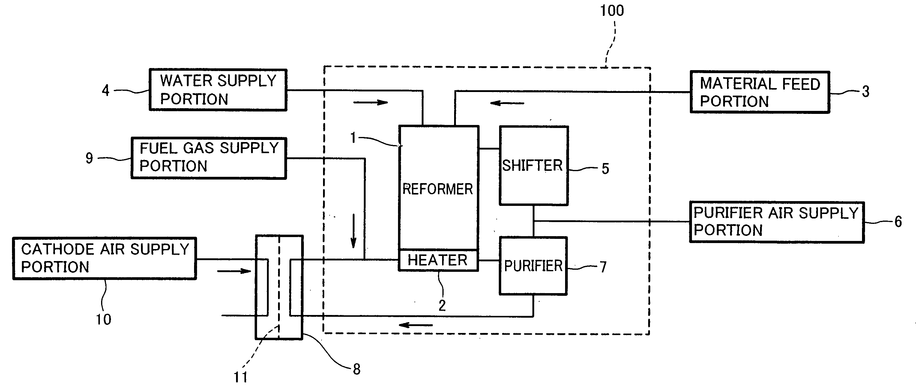
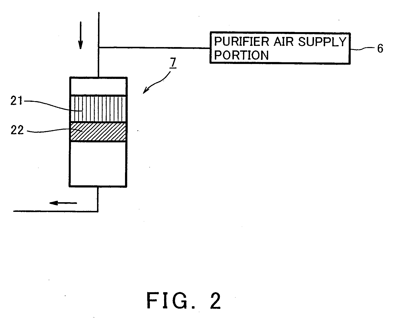
[0020] In accordance with this construction, during start of the hydrogen generator, even when the CO concentration of the reformed gas is high, oxygen remaining unconsumed after a reaction in the first catalyst body is consumed in the second catalyst body. Since the second catalyst body is located adjacent the first catalyst body, reaction heat in the second catalyst body is quickly transferred to the first catalyst body, it is possible to quickly increase the temperature of the first catalyst body. As a result, it is possible to start the hydrogen generator, and hence a fuel cell system comprising the hydrogen generator, without degrading catalyst activity.

Problems solved by technology

When using the reformed gas as the hydrogen source, in the case of a polymer electrolyte fuel cell operating at low temperatures lower than 100.degree. C., there is a possibility that platinum (Pt) based catalyst used as an electrode of the fuel cell is poisoned by carbon monoxide (CO) contained in the reformed gas.
When the Pt based catalyst is poisoned, reaction of hydrogen is obstructed, thereby significantly reducing power generation efficiency of the fuel cell.
Under this condition, oxidization reaction is difficult to progress even if air is supplied.
Since the catalysts are not sufficiently increased in temperature during start of the hydrogen generator, steam contained in the reformed gas condenses on the catalyst body, thereby leading to degraded catalyst, etc.
However, in the case of the hydrogen generator equipped with an electric heater, since the electric heater consumes an electric power, power generation efficiency decreases in a fuel cell system including the hydrogen generator.
In the hydrogen generator constructed as disclosed in the above-described Publications, sufficient performance is not obtained in the hydrogen generator, for example, selectivity of CO oxidization reaction is low.
In particular, in the hydrogen generator disclosed in the Publication No. 11-255512, since the catalyst body lower in CO selectivity than the CO selective oxidization catalyst is disposed on upstream side of the CO selective oxidization catalyst, air (oxygen) supplied from an air supply portion is consumed by reaction with hydrogen contained in the reformed gas in the catalyst body low in CO selectivity, so that CO selective oxidization reaction in the CO selective oxidization catalyst body is insufficient.
As a result, the CO concentration in the reformed gas cannot be sufficiently reduced.
During start of the hydrogen generator, if oxygen is not consumed in the purifier, the gas returning to the heater increases, thereby causing the reformer to be excessively heated, or oxidization and reduction are repeated in pipings in a subsequent stage of the hydrogen generator, where steam easily condenses, thereby causing corrosion to take place in the pipings.
However, since the electric heater consumes a considerable electric power, power generation efficiency in the fuel cell system is reduced.
In addition, when using the sensible heat of the exhaust gas, a structure of the gas flow passage becomes complex.
Therefore, oxidization reaction is difficult to progress in the CO selective oxidization catalyst body 21 in the purifier 7.
This unfavorably destroy a catalyst structure.
In particular, corrosion easily takes place in a portion where steam condenses when the fuel cell power generation system starts.
In such a case, adsorption of oxygen is obstructed.
Therefore, oxidization reaction of CO as well as reaction of hydrogen is difficult to occur.
And, steam is not supplied.
On the contrary, when the content of the noble metal is low, sufficient activity is not gained.

Method used


Image

  • Hydrogen generator and fuel cell system
  • Hydrogen generator and fuel cell system
  • Hydrogen generator and fuel cell system

Examples


example 1-2

[0084] In this embodiment, the oxygen removing catalyst body 22 was produced using each of ceria and iron oxide as a carrier, instead of the ceria-zirconia complex oxide. And, the hydrogen generator 100 was operated as in the example 1, and the start time was measured. As a result, the start time was 22 minutes.

[0085] As should be appreciated from the above, when using ceria or iron oxide as a carrier of the oxygen removing catalyst body 22, the start time can be reduced as in the case of using the ceria-zirconia complex oxide.

embodiment 2

[0086] (Embodiment 2)

[0087] A hydrogen generator according to a second embodiment of the present invention is constructed such that a CO methanation catalyst body is provided downstream of the oxygen removing catalyst body within the purifier. Since the other construction is identical to that of the first embodiment, its description is omitted.

[0088] FIG. 5 is a cross-sectional view schematically showing a construction of the purifier of the hydrogen generator according to the second embodiment of the present invention. With reference to FIGS. 1 and 5, the purifier 7 is cylindrical, and the CO selective oxidization catalyst body 21, the oxygen removing catalyst body 22, and the CO methanation catalyst body 23 are arranged in this order within the purifier from upstream side. The CO methanation catalyst body 23 has a function of removing CO in the reformed gas by converting CO and hydrogen into methane. Here, the CO methanation catalyst body 23 may be structured such that Ru carried ...

example 2

(Example 2)

[0096] Ru was carried on alumina at an amount of 1 wt-%, and the alumina carrying Ru thereon was calcined at 300.degree. C. in air. Alumina sol and pure water were added to the alumina and made into a slurry, which was coated on a cordierite honeycomb, thus producing the CO methanation catalyst body 23. The CO selective oxidization catalyst body 21 and the oxygen removing catalyst body 22 were produced as in the example 1.

[0097] The hydrogen generator 100 constructed as described above was operated as in the example 1, and start time was measured. The measurement was 29 minutes. And, the temperature of the CO methanation catalyst body 23 was 200.degree. C.


PUM

PropertyMeasurementUnit
temperaturesaaaaaaaaaa
temperatureaaaaaaaaaa
molar ratioaaaaaaaaaa

Abstract

A hydrogen generator comprises a reformer configured to generate a reformed gas containing at least hydrogen and carbon monoxide; a gas supply portion configured to supply an oxidization gas containing oxygen; a purifier configured to reduce a concentration of carbon monoxide contained in the reformed gas in such a manner that a mixture gas containing the reformed gas and the oxidization gas flows through the purifier such that the mixture gas flows through a catalyst body within the purifier to allow the carbon monoxide and the oxygen contained in the mixture gas to react with each other, wherein the purifier has a first catalyst body that selectively oxidizes the carbon monoxide and a second catalyst body which is lower in CO selectivity and lower in temperature of oxidization reaction than the first catalyst body, and the second catalyst body is disposed in parallel with the first catalyst body and on a downstream side of the first catalyst body or adjacent the first catalyst body in a flow of the mixture gas.

Description

[0001] 1. Field of the Invention[0002] The present invention relates to a hydrogen generator configured to generate a reformed gas to be supplied to a fuel cell, which contains hydrogen as a major component, and a fuel cell system comprising the hydrogen generator.[0003] 2. Description of the Related Art[0004] As a hydrogen source for use in a fuel cell or the like, a reformed gas obtained from a steam reforming reaction of an organic compound such as hydrocarbon, alcohol, or ether is commonly used. When using the reformed gas as the hydrogen source, in the case of a polymer electrolyte fuel cell operating at low temperatures lower than 100.degree. C., there is a possibility that platinum (Pt) based catalyst used as an electrode of the fuel cell is poisoned by carbon monoxide (CO) contained in the reformed gas. When the Pt based catalyst is poisoned, reaction of hydrogen is obstructed, thereby significantly reducing power generation efficiency of the fuel cell. To avoid this, it is ...

Claims


Application Information

Patent Timeline
Patent Type & Authority Applications(United States)
IPC IPC(8): B01D53/86B01J8/04C01B3/48C01B3/58H01M8/06
CPCB01D53/864B01J8/0453B01J2219/00006C01B3/48C01B3/583C01B2203/0233C01B2203/0283C01B2203/044C01B2203/0445C01B2203/0465C01B2203/047C01B2203/066C01B2203/0811C01B2203/0822C01B2203/0827C01B2203/1064C01B2203/107C01B2203/1082C01B2203/1241C01B2203/145C01B2203/146C01B2203/147C01B2203/1604H01M8/0612H01M8/0662Y02E60/50Y02P20/10H01M8/06
Inventor TAGUCHI, KIYOSHIUKAI, KUNIHIROWAKITA, HIDENOBUFUJIHARA, SEIJIKANI, YUKIMUNE
Owner PANASONIC CORP
Learn More