
Process for producing materials reinforced with nanoparticles and articles formed thereby

a technology of nanoparticles and reinforced materials, which is applied in the field of forming dispersions-strongened materials, can solve the problems of limited dispersion-strongening phase types, and achieve the effects of avoiding or at least reducing the cost of consolidation, machining, and other operations, and rapid solidification

Inactive Publication Date: 2005-01-06
GENERAL ELECTRIC CO
View PDF6 Cites 20 Cited by
  • Summary
  • Abstract
  • Description
  • Claims
  • Application Information

AI Technical Summary

Benefits of technology

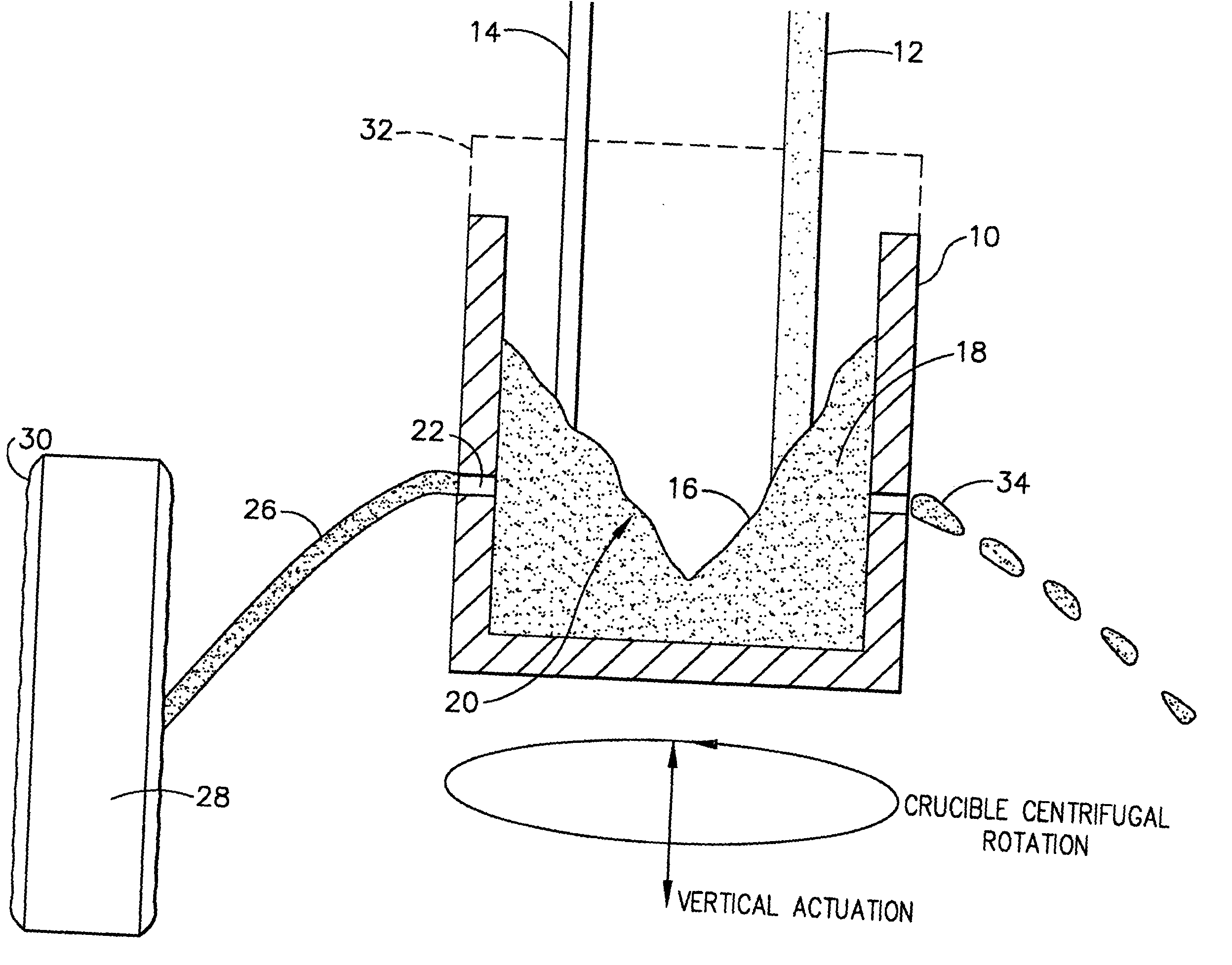
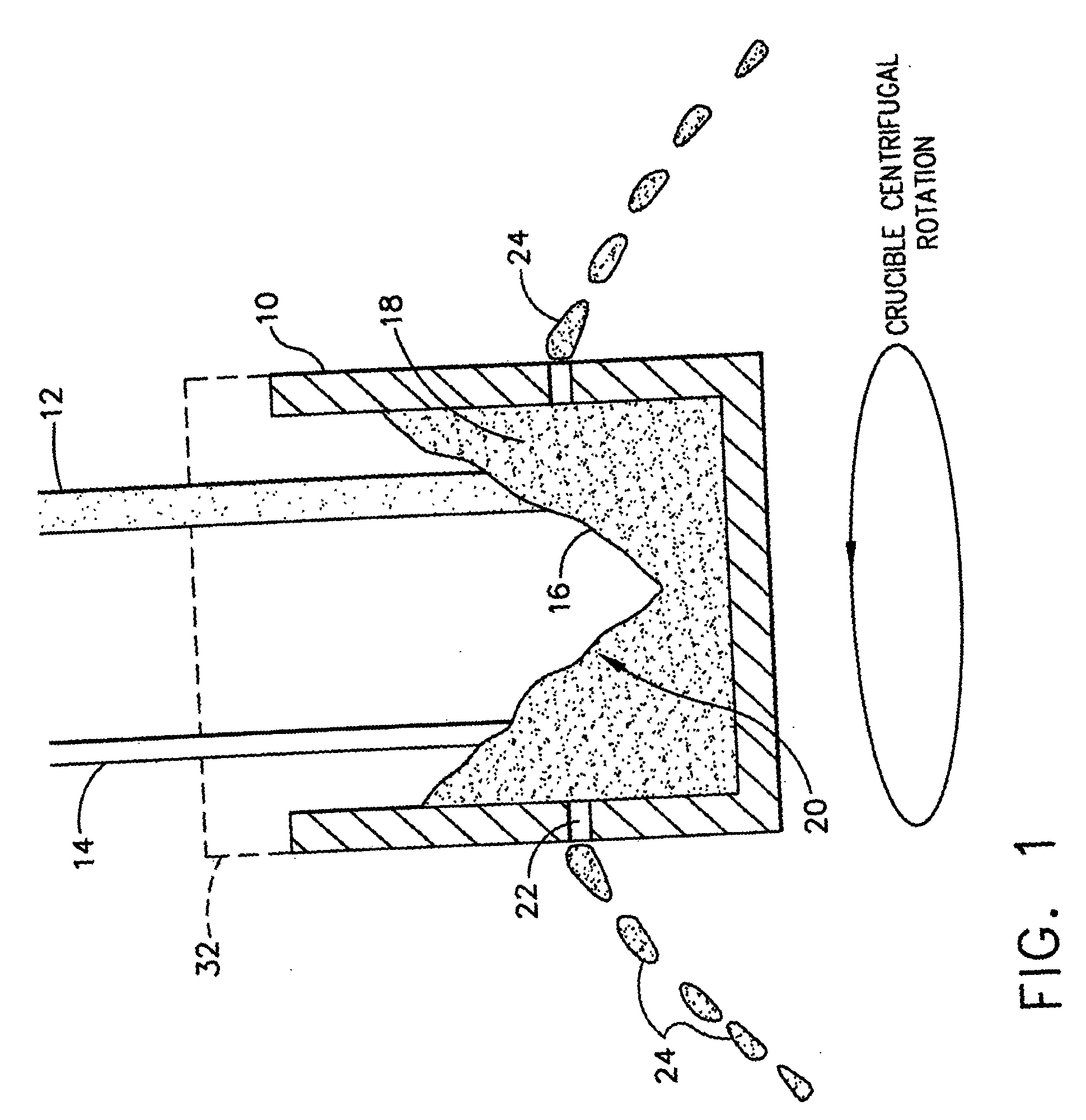
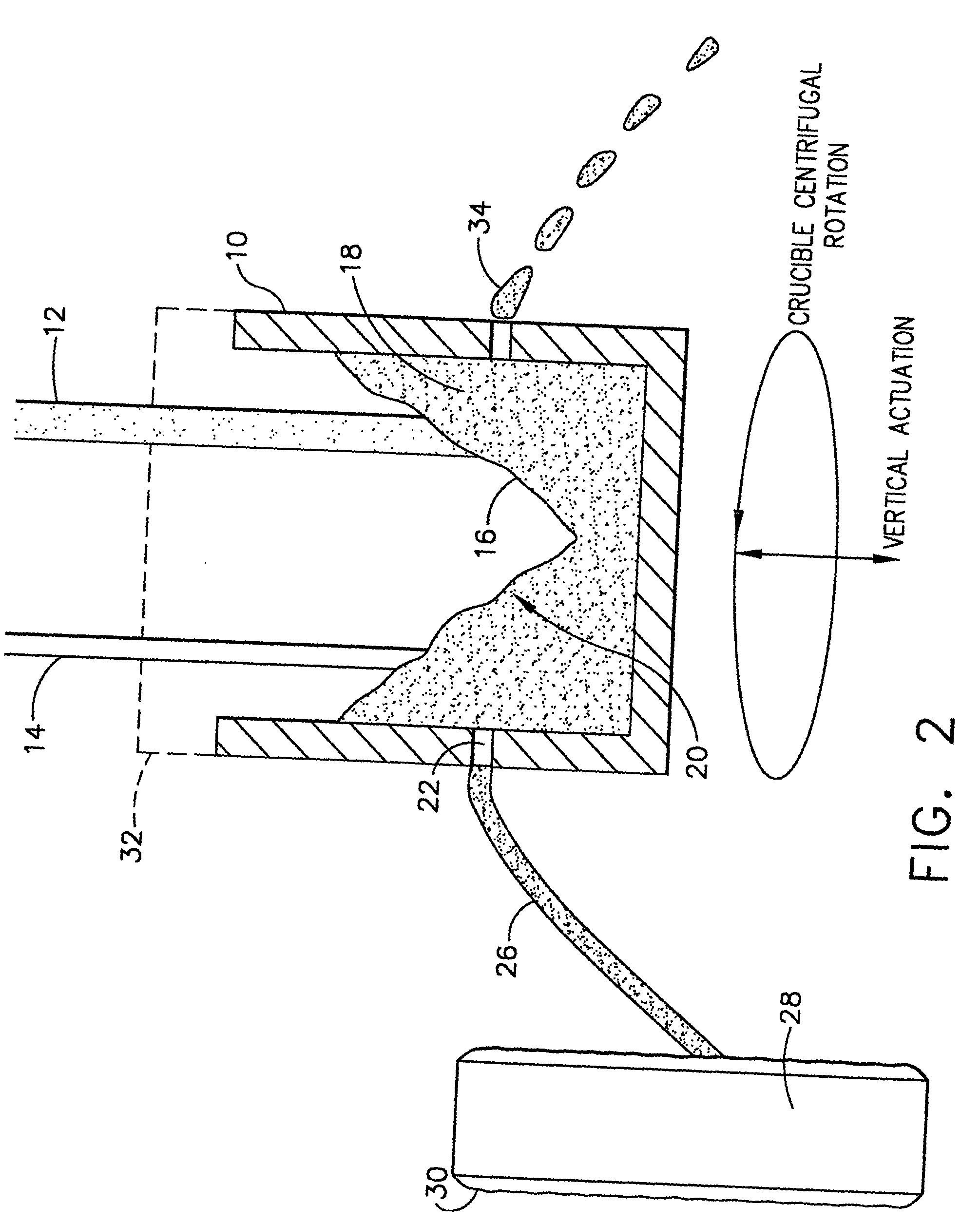
[0006] According to one aspect of the invention, the molten composite material solidifies to form the solid composite body by contacting a surface (e.g., of a mold) after being ejected from the container. In this manner, the molten composite material is effectively centrifugally spin-cast directly onto the surface. If the surface is that of an appropriately configured mold, the resulting solid composite body can be in the form of a near-net-shape body, a preform or mill product (e.g., a slab, plate or ring). According to another aspect of the invention, the molten composite material solidifies in-flight after being ejected from the container, such that the molten composite material is centrifugally spin-cast into a finely divided form, such as powder particles, flakes, wires or ribbons. Any one or more of these finely-divided forms can be consolidated by thermomechanical techniques (e.g., hot pressing, sintering, HIPing, extrusion, forging, etc.) into bulk near-net-shape components, preforms, or mill product forms containing well-dispersed nanoparticles. Whether the intent is to produce a dispersion-strengthened solid composite body in bulk or finely-divided form, centrifugal mixing of the nanoparticles in the molten material serves to uniformly disperse the nanoparticles, and rapid solidification of the resulting molten composite material initiated by centrifugal ejection from the mixing container ensures that the nanoparticles remain substantially uniformly dispersed during solidification, so that the nanoparticles are also uniformly dispersed in the resulting solid composite body.

Problems solved by technology

The type of dispersion strengthening phase is limited only by availability and compatibility with the matrix phase.

Method used


Image

  • Process for producing materials reinforced with nanoparticles and articles formed thereby
  • Process for producing materials reinforced with nanoparticles and articles formed thereby
  • Process for producing materials reinforced with nanoparticles and articles formed thereby

Examples


Embodiment Construction

[0011]FIGS. 1 and 2 schematically represent two techniques of this invention by which dispersion-strengthened materials are produced, in which the dispersion reinforcement material includes or is formed entirely of nano-sized dispersoid particles (nanoparticles). In the embodiment represented in FIG. 1, nanoparticles 12 and a molten material 14 are delivered in separate streams to form a pool 16 of molten composite material 18 contained by a crucible 10. As the nanoparticles and molten material 12 and 14 are added to the pool 16, the crucible 10 is caused to spin, rotating about its vertical axis, such as by mounting the crucible 10 to a spinning pedestal (not shown). As will be known by those skilled in the art, crucible materials, crucible constructions, and equipment suitable for this purpose will depend on the type and amount of materials used.

[0012] The crucible 10 is caused to spin at a sufficient rate so that the centrifugal force applied by the nanoparticle-filled molten co...


PUM

PropertyMeasurementUnit
sizeaaaaaaaaaa
sizeaaaaaaaaaa
volume fractionaaaaaaaaaa

Abstract

A method for forming a dispersion-strengthened material containing nanoparticles that are uniformly dispersed in a matrix phase. The method includes adding nanoparticles and a molten material to a container to form a pool within the container and rotating the container to create a convection vortex in the pool. The convection vortex is sufficient to cause the nanoparticles to be incorporated into the molten material so as to yield a molten composite material, and further causes the molten composite material to be ejected from the container. The molten composite material is then cooled to form a solid composite body comprising a uniform dispersion of the nanoparticles.

Description

BACKGROUND OF THE INVENTION [0001] The present invention generally relates to a process for forming dispersion-strengthened materials. More particularly, this invention relates to a process for dispersing nanoparticles within a liquid-phase material, such as a molten metal, which on solidification yields a body having a uniform dispersion of the nanoparticles. BRIEF DESCRIPTION OF THE DRAWINGS [0002] Dispersion strengthening phases that are relatively stable in metallic systems are of interest for a variety of structural applications. The potent strengthening effect of AlN precipitates in bulk beta-NiAl alloys and of oxide dispersion-strengthening (ODS) in superalloys has been demonstrated. Examples of the latter include the commercially-available MA754 and MA6000 alloys. To provide a sufficient level of dispersion strengthening, fine dispersoid particles (such as oxides, nitrides, etc.) must be present in a volume fraction and distribution such that the mean free path between parti...

Claims


Application Information

Patent Timeline
Patent Type & Authority Applications(United States)
IPC IPC(8): B22D13/08B22F3/115B22F9/10C22C1/05C22C1/10
CPCB22D13/08B22F3/115B22F2998/00B22F2999/00C22C1/1042B22F9/10
Inventor HUANG, SHYH-CHINSUBRAMANIAN, PAZHAYANNUR RAMANATHANZABALA, ROBERT JOHNPETTERSON, ROGER JOHNOTT, ERIC ALLENGOWDA, SRINIVASA RANGE
Owner GENERAL ELECTRIC CO
Learn More