Objective lens for optical pick-up

Inactive Publication Date: 2005-01-06
HOYA CORP
View PDF9 Cites 26 Cited by
  • Summary
  • Abstract
  • Description
  • Claims
  • Application Information

AI Technical Summary

Benefits of technology

For this reason, the objective lens according to the above mentioned aspect of the invention is used in a situation where the substantially collimated light beam is incident on the objective lens when one of the first and second optical discs, each of which requires a relatively high numerical aperture, is used, and the diverging beam is incident on the objective lens when the third optical disc, which requires a relatively low numerical aperture, is used. With this structure, even if the objective lens is shifted from an optical axis thereof by the tracking operation, the amount of the coma and astigmatism caused when the first or second optical disc is used can be lowered to a negligible level.
An refractive index of a coupling lens, which may be used together with the objective lens in the

Problems solved by technology

However, the objective lens disclosed in the publication No. 2000-81566 is not configured to support the HD DVD.
That is, when the blue laser beam is incident on the objective lens disclosed in the publication, aberrations including a spherical aberration are caused and therefore a beam spot suitable for the recordation and the reproduction of data of the HD DVD can not be formed.
However, in this publication no explanat

Method used


Image

  • Objective lens for optical pick-up
  • Objective lens for optical pick-up
  • Objective lens for optical pick-up

Examples


Example

FIRST EXAMPLE

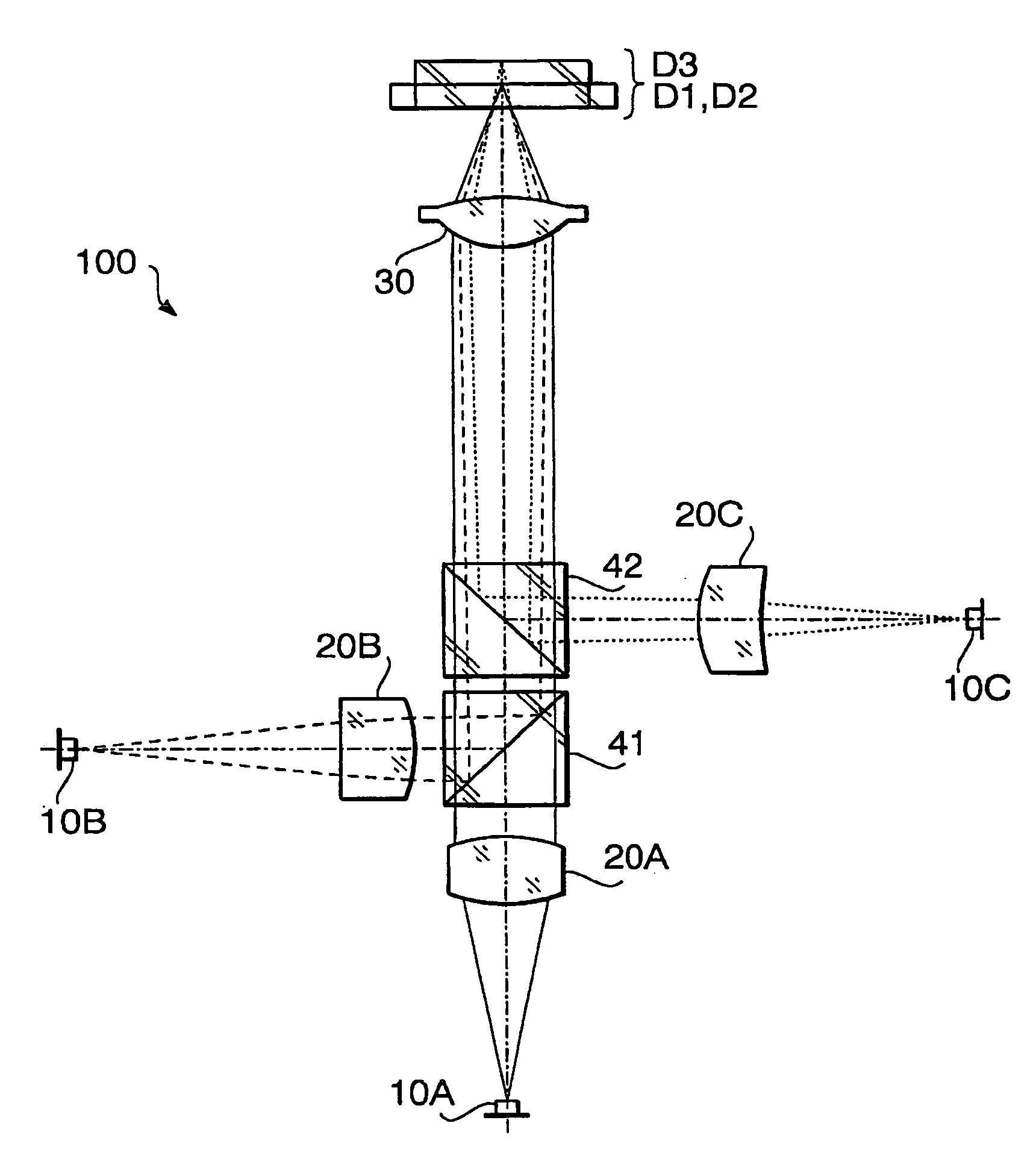
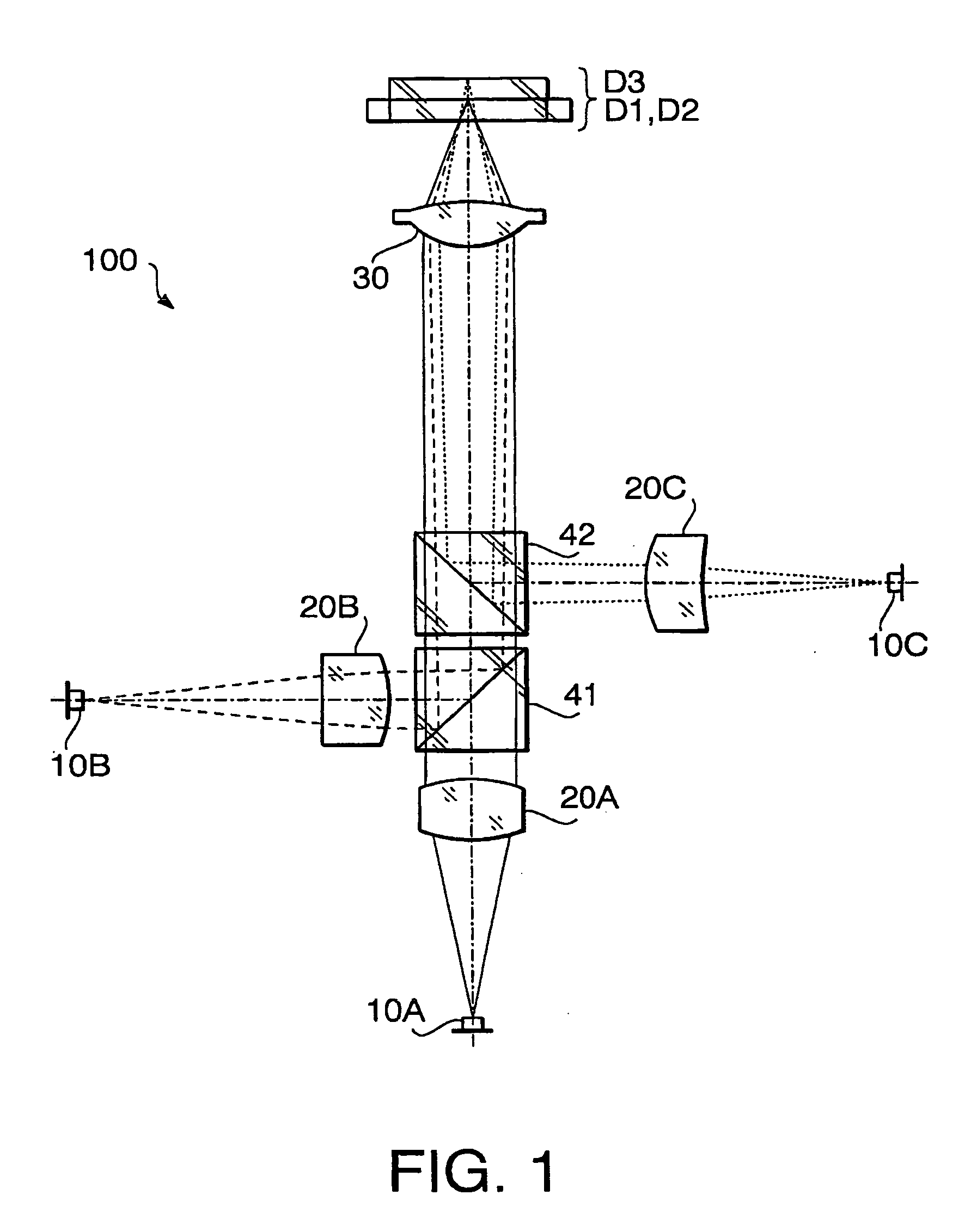
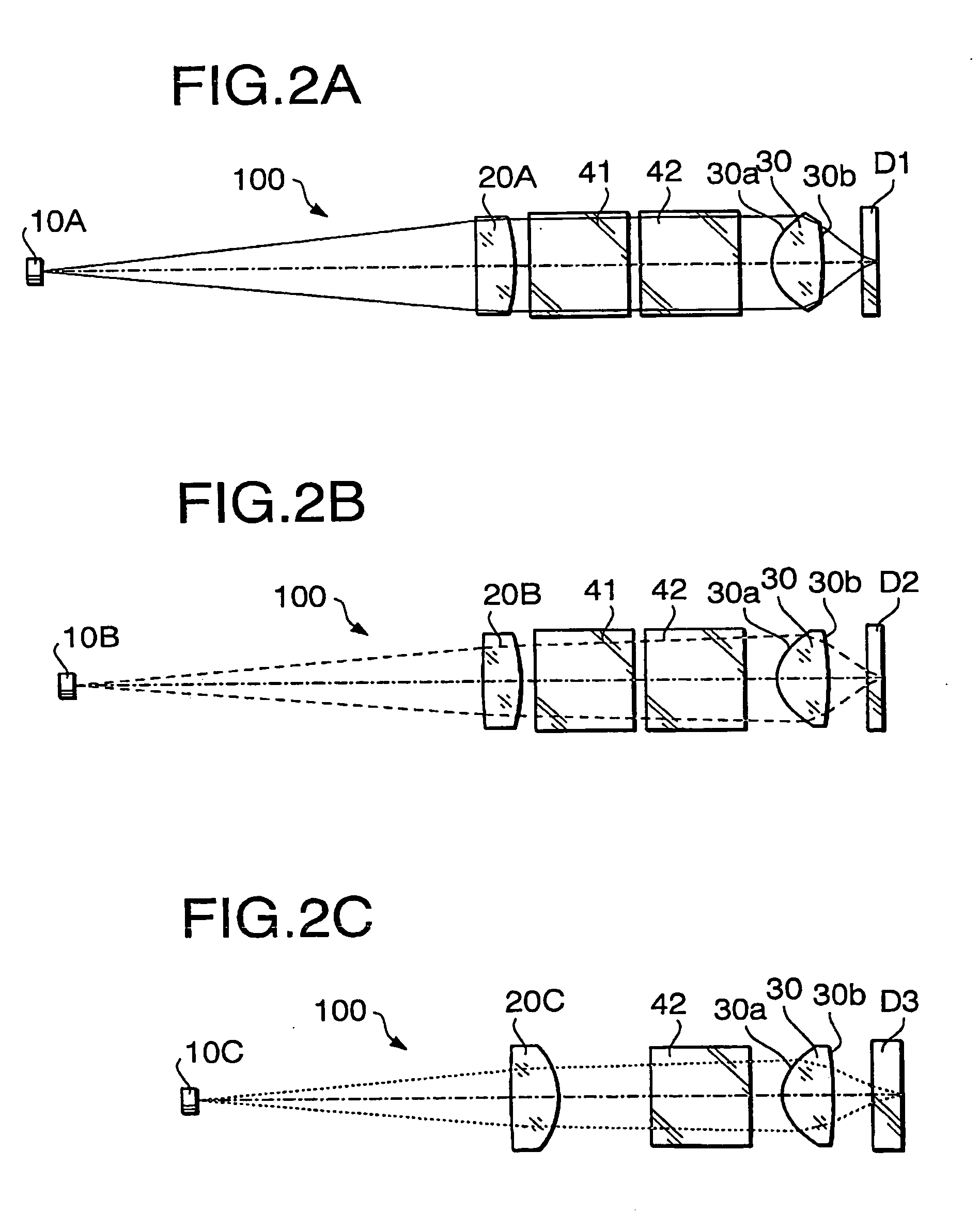
The optical pick-up 100 according to a first example has the configuration shown in FIGS. 1 and 2. Performance specifications of the objective lens 30 according to the first example are shown in Table 1. TABLE 1First laserSecond laserThird laserbeambeambeamDesign405nm657nm785nmwavelengthf3.004mm3.108mm3.130mmFocal lengthNA0.6490.6020.451magnification0.0000.000−0.074

In Table 1 (and in the following similar Tables), the design wavelength is a wavelength suitable for the recordation / reproduction of the optical disc, f represents a focal length (unit: mm) of the objective lens 30, NA represents the numerical aperture. In Table 1, the performance specifications are indicated with regard to each of the first laser beam (the optical disc D1), the second laser beam (the optical disc D2) and the third laser beam (the optical disc D3).

Table 2 shows a numerical configuration of the optical pick-up 100 when the optical disc D1 (the first laser beam) is used, Table 3 shows a n...

Example

SECOND EXAMPLE

Hereafter, the optical pick-up 100 according to a second example will be described. The optical pick-up 100 according to the second example has a configuration substantially the same as that of the first example. That is, the numerical data shown in Tables 1-9 is also applied to the second example. Only the diffracting structure formed within the first surface 30a of the objective lens 30 is different from that of the first example.

The objective lens 30 according to the second example has the diffracting structure shown in FIG. 4. Table 10 shows numerical data of the diffracting structure formed on the first surface 30a of the objective lens 30. TABLE 10La (unit: λ1)FromAnnularFromadjacentzoneannularannularNo.HsHezone #0zone #00.0000.9770First #10.9771.205−8−8Region #21.2051.346−62 #31.3461.449−14−8 #41.4491.530−122 #51.5301.601−15−3Second #61.6011.661−18−3Region #71.6611.713−21−3 #81.7131.759−24−3 #91.7591.801−27−3#101.8011.839−30−3#111.8391.870−33−3#121.8701.905...

Example

THIRD EXAMPLE

The optical pick-up 100 according to a third example will be described. The configuration of the optical pick-up 100 according to the third example is shown in FIG. 1. In this example, configurations of the coupling lens 20A and the coupling lens 20B are the same. Therefore, the coupling lens 20A and the coupling lens 20B are referred to as a coupling lens 200A_1 and a coupling lens 200A_2, respectively, in this example. FIG. 8A shows a configuration of the optical pick-up 100 when the optical disc D1 is used, FIG. 8B shows a configuration of the optical pick-up 100 when the optical disc D2 is used, and FIG. 8C shows a configuration of the optical pick-up 100 when the optical disc D3 is used.

Performance specifications of the objective lens 30 according to the third example are shown in Table 11. TABLE 11First laserSecond laserThird laserbeambeambeamDesign405nm657nm785nmwavelengthf3.000mm3.108mm3.121mmFocal lengthNA0.6500.6270.500magnification0.0000.000−0.086

As sho...


PUM


Abstract

An objective lens that satisfies conditions:
−0.02<fM1<0.02  (1)
−0.02<fM2<0.02  (2)
−0.29<fM3<−0.19  (3).
At least one of lens surfaces of the objective lens includes a diffracting structure having a first region for converging the third light beam on a data recording layer of the third optical disc. The diffracting structure within the first region is configured such that a diffraction order at which diffraction efficiency of the first light beam is maximized is a sixth order, a diffraction order at which the diffraction efficiency of the second light beam is maximized is a fourth order, and a diffraction order at which the diffraction efficiency of the third light beam is maximized is a third order.

Description

BACKGROUND OF THE INVENTION The present invention relates to an objective lens for an optical pick-up used for an optical disc drive, which is capable of recording data to and / or reproducing data from a plurality of types of optical discs having different recording densities and having different thicknesses of cover layers. There are various types of optical discs on which digital information is recorded at various densities, respectively. For example, a DVD (digital versatile disc) has a recording density higher that that of a CD (compact disc) or a CD-R (CD Recordable) and has a cover layer thinner than that of the CD or CD-R. When the recording / reproducing for the DVD having a higher recording density is performed, a smaller beam spot diameter is required on the data recording layer of the DVD relative to a beam spot used for the CD having a lower recording density. For this reason, the optical pick-up is configured such that a NA (numerical aperture) is changed to a higher va...

Claims


Application Information

Patent Timeline
IPC IPC(8): G02B13/14G02B27/00G11B7/00G11B7/135
CPCG02B5/188G02B5/1895G02B13/146G11B2007/0006G02B27/4238G11B7/1353G11B7/1374G02B27/0037
Inventor MARUYAMA, KOICHIKOREEDA, DAISUKE
Owner HOYA CORP
Why Eureka
Try Eureka