Devices, systems, and methods to fixate tissue within the regions of body, such as the pharyngeal conduit

a technology of pharyngeal conduit and tissue fixation device, which is applied in the direction of snoring prevention, prosthesis, therapy, etc., can solve the problems of affecting the quality of life of patients, so as to improve the effect of

Inactive Publication Date: 2005-01-06
KONINKLIJKE PHILIPS ELECTRONICS NV
View PDF34 Cites 161 Cited by
  • Summary
  • Abstract
  • Description
  • Claims
  • Application Information

AI Technical Summary

Benefits of technology

[0020] One aspect of the invention provides systems and methods that include implant structures, and / or implantation devices, and / or surgical implantation techniques, which make possible the treatment of physiologic conditions with enhanced effectiveness.
[0025] Another aspect of the invention provides a focused magnetic implant. The implant comprises a structure sized and configured to be implanted in animal tissue. The structure including at least one magnet made from a hard ferromagnetic material and a flux shield comprising a soft ferromagnetic material overlaying at least a portion of the magnet. The flux shield focuses and enhances the magnetic field of the magnet in directions that the shield does not overlay.
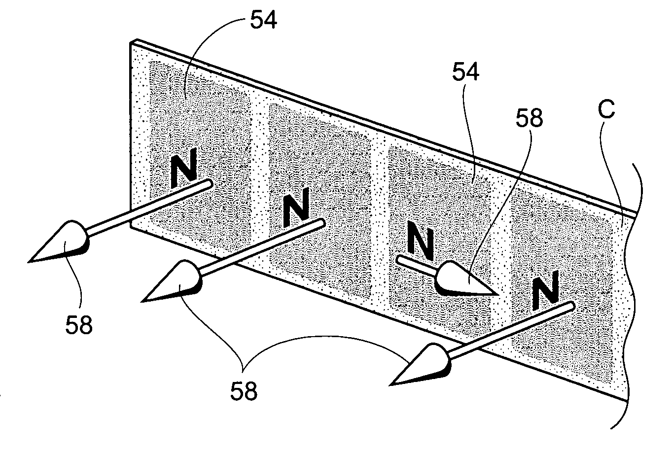
[0026] Another aspect of the invention provides a stablized magnetic implant. The implant comprising a structure sized and configured to be implanted in animal tissue. The structure includes at least one magnet made from a hard ferromagnetic material having a desired magnetic pole. At least one stabilization magnet is provided having a magnetic pole that is the same as the desired magnetic pole and that is oriented normal or at an acute angle to the desired magnetic pole. Should rotational misalignment of the implant relative to another magnetic implant occur, the presence of the stabilizing magnet keeps the magnetic field forces aligned. As a result, destabilizing magnetic fields are reduced due to misalignment.

Problems solved by technology

Sleep apnea is a common but serious, potentially life-threatening condition, affecting as many as 18 million Ameritans.
When the muscles of the upper airway relax and sag, the relaxed. tissues may vibrate as air flows past the tissues during breathing, resulting in snoring.
In more serious cases, the airway becomes blocked, making breathing labored and noisy, or even stopping it altogether.
Lack of air intake into the lungs results in lower levels of oxygen and increased levels of carbon dioxide in the blood.
The frequent interruptions of deep, restorative sleep often lead to early morning headaches, excessive daytime sleepiness, depression, irritability, and learning and memory difficulties.
There are potentially damaging effects to the heart and blood vessels due to abrupt compensatory swings in blood pressure.
Upon each event, the sleeping person will be partially aroused from sleep, resulting in a greatly reduced quality of sleep and associated daytime fatigue.
Although some apneic events are normal in all humans, the frequency of blockages will determine the seriousness of the disease and opportunity for health damage.
The upper airway, therefore, has the greatest potential for collapse and closure at end-expiration.
It can be cumbersome to wear and travel with, difficult to accept on a social level, and not tolerated by many (for reasons such as claustrophobia, facial and nasal mask pressure sores, airway irritation).
These factors have lead to a relatively poor long-term compliance rate.

Method used


Image

  • Devices, systems, and methods to fixate tissue within the regions of body, such as the pharyngeal conduit
  • Devices, systems, and methods to fixate tissue within the regions of body, such as the pharyngeal conduit
  • Devices, systems, and methods to fixate tissue within the regions of body, such as the pharyngeal conduit

Examples


example 1

Unshielded Core

[0114]FIG. 14A shows a core 48 comprising a permanent magnet measuring 40 mm×40 mm×25 mm (i.e., a volume of 40,000 mm3 ). FIG. 14B shows the total flux density distribution on the YZ plane, based upon finite element modeling, of the magnetic field generated by the permanent magnet. FIG. 14B shows the magnetic field emanating in all directions in the YZ plane about the magnet. FIG. 14C shows the magnitude of the Z component of flux density (Bz) taken at increasing distances from the top magnet surface along its center line. FIG. 14C generally shows a bell shaped curve, with a maximum Bz(T) of 0.6 at a distance of about 62 mm from the magnet surface, with gradual increases with decreasing distances and gradual decreases with increasing distances.

example 2

Shielded Core

[0115]FIG. 15A shows a core 48 comprising a permanent magnet smaller than the magnet of Example 1, measuring 30 mm×30 mm×20 mm (i.e., having a lesser volume of 18,000 mm3 ). The magnet has been placed within a flux shield 50. The flux shield comprises a box made from a soft ferromagnetic material. The box covers all but one pole surface of the permanent magnet.

[0116]FIG. 15B shows the total flux density distribution on the YZ plane, based upon finite element modeling, of the magnetic field generated by the permanent magnet when housed within the box. FIG. 15B shows that the presence of the ferromagnetic material of the box significantky alters the distribution pattern of the flux density of the field on the YZ plane. The magnetic field is demonstrably focused in the direction of the field that is not shielded by the ferromagnetic material. FIG. 15C shows the magnitude of the Z component of flux density (Bz) taken at increasing distances from the unshielded pole surfac...

example 3

Alternative Shielded Magnets

[0118]FIGS. 16A and 16B show alternative embodiments of magnetic cores 48 comprising permanent magnets with flux shields 50 of soft ferromagnetic materials. Finite element analysis of these alternative embodiments show the focused flux density distribution shown in FIG. 15B, as well as the spike-curve configuration, shown in FIG. 15C, of the Z component of flux density (Bz) taken at increasing distances from the unshielded magnet pole along its center line.

EXAMPLE 4

Single Pole Shield

[0119]FIG. 17A shows magnetic core 48 comprising a permanent magnet having generally the same measurements as the magnet in Example 1. In this embodiment, the flux shield 50 overlays only one pole of the magnet. FIG. 17B shows that the magnitude of the Z component of flux density (Bz) taken at increasing distances from the unshielded magnet pole along its center line has been ltered by the presence of the single pole flux shield 50. FIG. 17B shows the same spike-curve confi...


PUM


Abstract

Systems and methods incorporate implant structures, and / or implantation devices, and / or surgical implantation techniques, to make possible the treatment of physiologic conditions, such as sleep disordered breathing, with enhanced effectiveness.

Description

RELATED APPLICATIONS [0001] This application claims the benefit of U.S. patent application Ser. No. 10 / 718,254, filed Nov. 20, 2003 and entitled “Devices, Systems, and Methods to Fixate Tissue Within the Regions of the Body, Such as the Pharyngeal Conduit”; U.S. patent application Ser. No. 10 / 656,861, filed Sep. 6, 2003 and entitled “Magnetic Force Devices, Systems, and Methods for Resisting Tissue Collapse within the Pharaygeal Conduit”; U.S. patent application Ser. No. 10 / 236,455, filed Sep. 6, 2002 and entitled “Systems and Methods for Moving and / or Restraining Tissue in the Upper Respiratory System”; and U.S. Provisional Patent Application Ser. No. 60 / 441,639, filed Jan. 22, 2003 and entitled “Magnetic Splint Device and Method for the Treatment of Upper Airway Collapse in Obstructive Sleep Apnea;” and U.S. Provisional Patent Application Ser. No. 60 / 456,164, filed Mar. 20, 2003 and entitled “Device and Method for Treatment of Sleep Related Breathing Disorders Including Snoring an...

Claims


Application Information

Patent Timeline
Patent Type & Authority Applications(United States)
IPC IPC(8): A61F2/00A61F5/56
CPCA61F2/00A61F5/566A61F5/56Y10S602/902
Inventor NELSON, LIONEL M.LIU, JINFANGBOUCHER, RYAN P.DOELLING, ERIC N.STINE, J. GREGJONES, LAWRENCE R.
Owner KONINKLIJKE PHILIPS ELECTRONICS NV
Why Eureka
Try Eureka