Designs for left ventricular conduit

Inactive Publication Date: 2005-01-06
HORIZON TECH FUNDING CO LLC
View PDF9 Cites 39 Cited by
  • Summary
  • Abstract
  • Description
  • Claims
  • Application Information

AI Technical Summary

Benefits of technology

[0011] The stent can be self-expandable or expanded by means of a balloon or similar device, and can be provided with various means to anchor it in position within the myocardium, such as expandable legs, hooks, barbs, collars, suture holes and the like. The stent

Problems solved by technology

Coronary artery disease is a major problem in the U.S. and throughout the world.
Coronary arteries as well as other blood vessels frequently become clogged with plaque, which at the very least impairs the efficiency of the heart's pumping action, and can lead to heart attack and death.
In more difficult cases, a bypass of the blocked vessel is necessary.
Such coronary artery bypass surgery, however, is a very

Method used


Image

  • Designs for left ventricular conduit
  • Designs for left ventricular conduit
  • Designs for left ventricular conduit

Examples


first embodiment

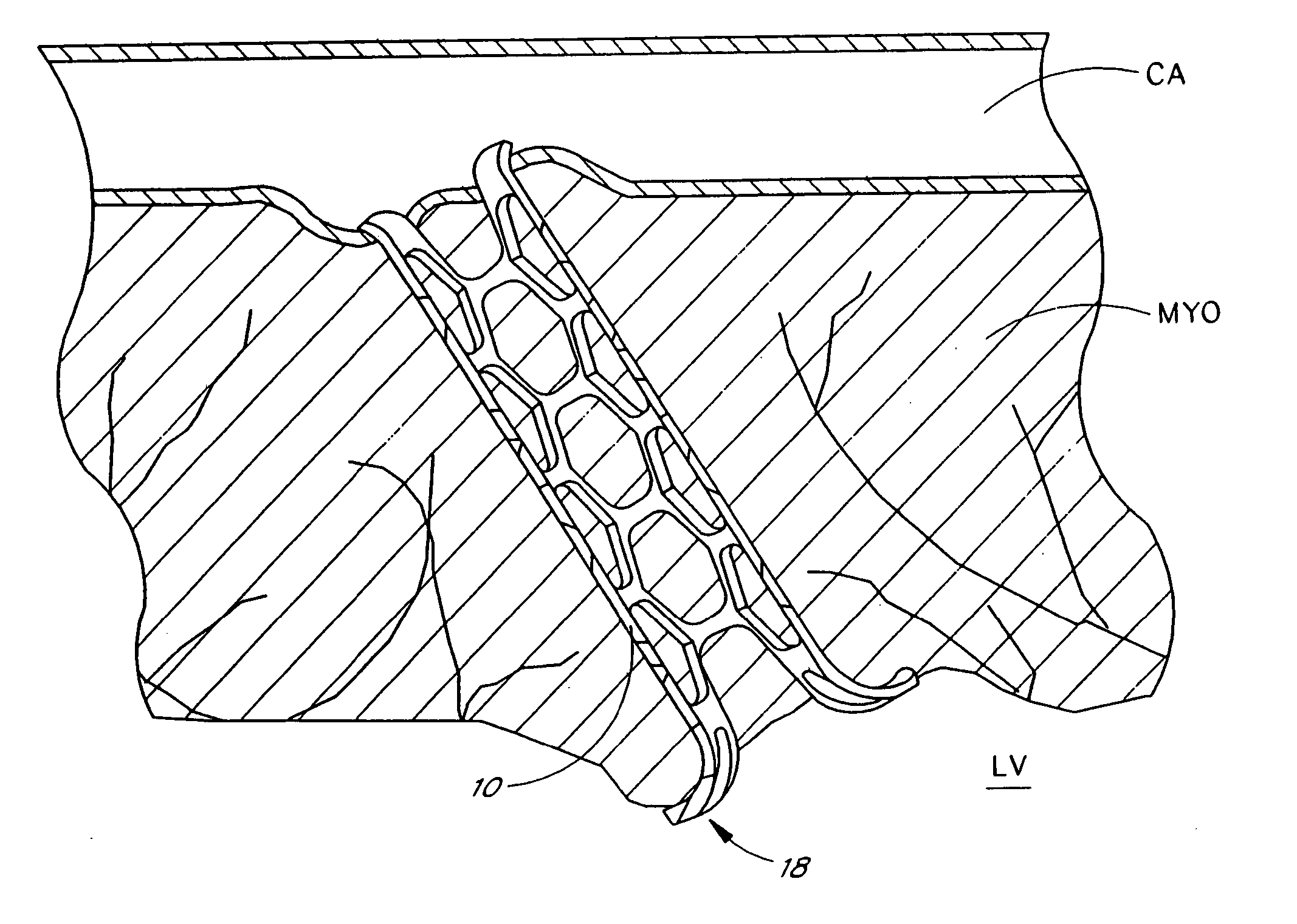
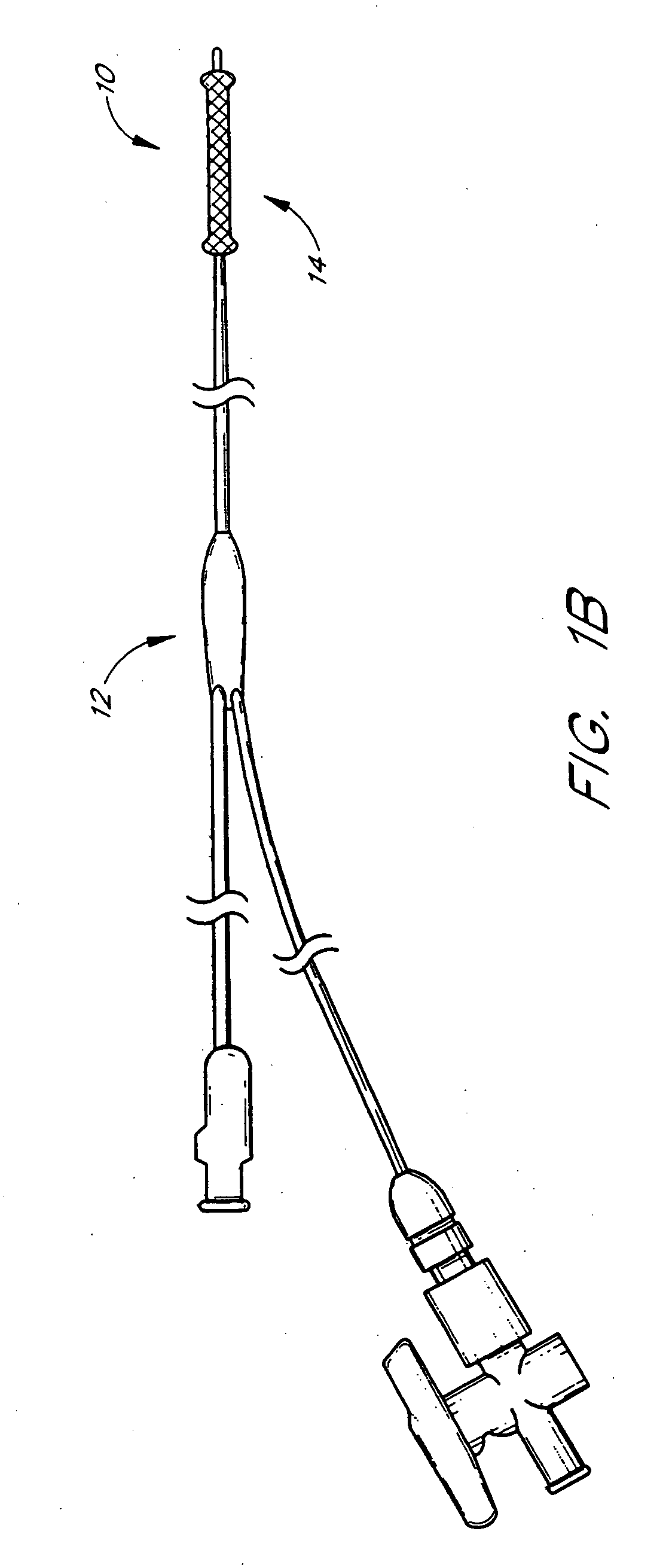
[0049] the present invention is illustrated in FIG. 1B. This embodiment is a balloon-expanded stent 10. The stent 10 is introduced as described below, using a high-pressure balloon catheter 12 to deploy the stent 10 once it is properly positioned in the myocardium MYO (FIG. 2). When the stent 10 is positioned inside the myocardial wall MYO, the balloon 14 is inflated to expand the stent 10 and open the conduit from the left ventricle LV into the coronary artery CA. The stent 10 can include attachment mechanisms not limited to hooks, barbs, flanges, large collars, suture holes and / or other means to ensure a seal is created between the coronary artery CA and the wall of the myocardium MYO and to prevent the threat of stent 10 migration. When the attachment of the stent 10 is completed, the remaining catheter assembly 12 is removed, leaving the stent 10 in place. Upon deflating the balloon 14, the stent 10 will remain open. Because of the shape of this stent 10, a dumbbell shaped ballo...

second embodiment

[0052] the stent or conduit incorporates a self-expanding stent 20, illustrated in FIGS. 5-8. The stent 20, having a retaining sheath 26 to hold it in a non-expanded configuration, is introduced into the wall of the myocardium MYO as follows. The stent delivery catheter 22 is advanced over a puncture mechanism 24 and into the wall of the myocardium MYO as described above. When the stent 20 is properly seated in the myocardial wall MYO, its retaining sheath 26 is withdrawn, allowing the stent 20 to expand and open a conduit from the ventricle LV to the coronary artery CA. This stent 20 also includes attachment mechanisms not limited to hooks, barbs, flanges, large collars, suture holes and / or other means to ensure a seal is created between the artery CA and the wall of the myocardium MYO, and to prevent the threat of stent 20 migration. When the positioning is completed, the remaining catheter assembly 22 is removed, leaving the stent 20 in place.

[0053] The self-expanding stent 20 mo...

third embodiment

[0055] the stent design, illustrated in FIGS. 9-11, incorporates attachment flanges or “legs”30 that expand after introduction into the myocardium to hold the stent 34 in place. The puncture instrument 32 and stent 34 are mated together and are advanced into the myocardial wall as a single unit. The puncture instrument's distal end 36 is shaped in a “nose-cone” configuration, which is responsible for containing the legs 30 of the stent 34 while it is being introduced into the wall of the myocardium. When the stent 34 is in the proper position in the myocardial wall, the nose cone 36 is pushed forward, releasing the attachment legs 30 of the stent 34. The internal diameter (ID) of the stent 34 is large enough to allow the nose cone 36 to pass back through. The stent 34 is then released from the catheter 38 and the catheter 38 is removed.

[0056]FIG. 9 illustrates the stent 34 mounted on the introducer catheter 38. The expanding legs 30 of the stent 34 are held in place by the nose cone...


PUM


Abstract

A conduit is provided to provide a bypass around a blockage in the coronary artery. The conduit is adapted to be positioned in the myocardium or heart wall to provide a passage for blood to flow between a chamber of the heart such as the left ventricle and the coronary artery, distal to the blockage. The stent is self-expanding or uses a balloon to expand the stent in the heart wall. Various attachment means are provided to anchor the stent and prevent its migration.

Description

CROSS-REFERENCE TO RELATED APPLICATIONS [0001] This application claims the benefit of U.S. Provisional Applications Ser. Nos. 60 / 099,767, filed Sep. 10, 1998, and 60 / 104,397, filed Oct. 15, 1998.FIELD OF THE INVENTION [0002] The present invention relates to an apparatus for bypassing a blocked blood vessel segment, and, more particularly, to a conduit or stent positioned between the coronary artery or other blocked vessel and a chamber of the heart, such as the left ventricle of the heart, to bypass a blocked segment of the coronary artery or other blood vessel.BACKGROUND OF THE INVENTION [0003] Coronary artery disease is a major problem in the U.S. and throughout the world. Coronary arteries as well as other blood vessels frequently become clogged with plaque, which at the very least impairs the efficiency of the heart's pumping action, and can lead to heart attack and death. In some cases, these arteries can be unblocked through non-invasive techniques such as balloon angioplasty....

Claims


Application Information

Patent Timeline
IPC IPC(8): A61B17/00A61B17/22A61F2/00A61F2/02A61F2/82A61F2/94A61F11/00
CPCA61B17/3207A61F2230/006A61B2017/22077A61F2/2493A61F2/82A61F2/91A61F2/915A61F2/94A61F2/95A61F2/958A61F2002/826A61F2002/91541A61F2250/0067Y10S623/903A61F2220/0008A61F2220/0016A61F2230/005A61B2017/00252
Inventor PHELPS, DAVID Y.FURNISH, GREG R.HALL, TODD A.GRIFFIN, MARKWOLF, SCOTT J.WILK, PETER J.SCHMELTER, JAYFURNISH, SIMON
Owner HORIZON TECH FUNDING CO LLC
Why Eureka
Try Eureka