
Process and apparatus for energy storage and release

a technology of energy storage and release, applied in the field of carbon nanotubes, can solve the problems of damage to carbon nanotubes, ineffective fuel cell applications, and slow rendering of adsorption or absorbed gas by conventional desorption techniques, so as to increase the purity reduce the diameter of nanotubes in samples, and increase the density of carbon nanotube samples

Undetermined Publication Date: 2005-01-13
PENN STATE RES FOUND +1
View PDF7 Cites 29 Cited by
  • Summary
  • Abstract
  • Description
  • Claims
  • Application Information

AI Technical Summary

Benefits of technology

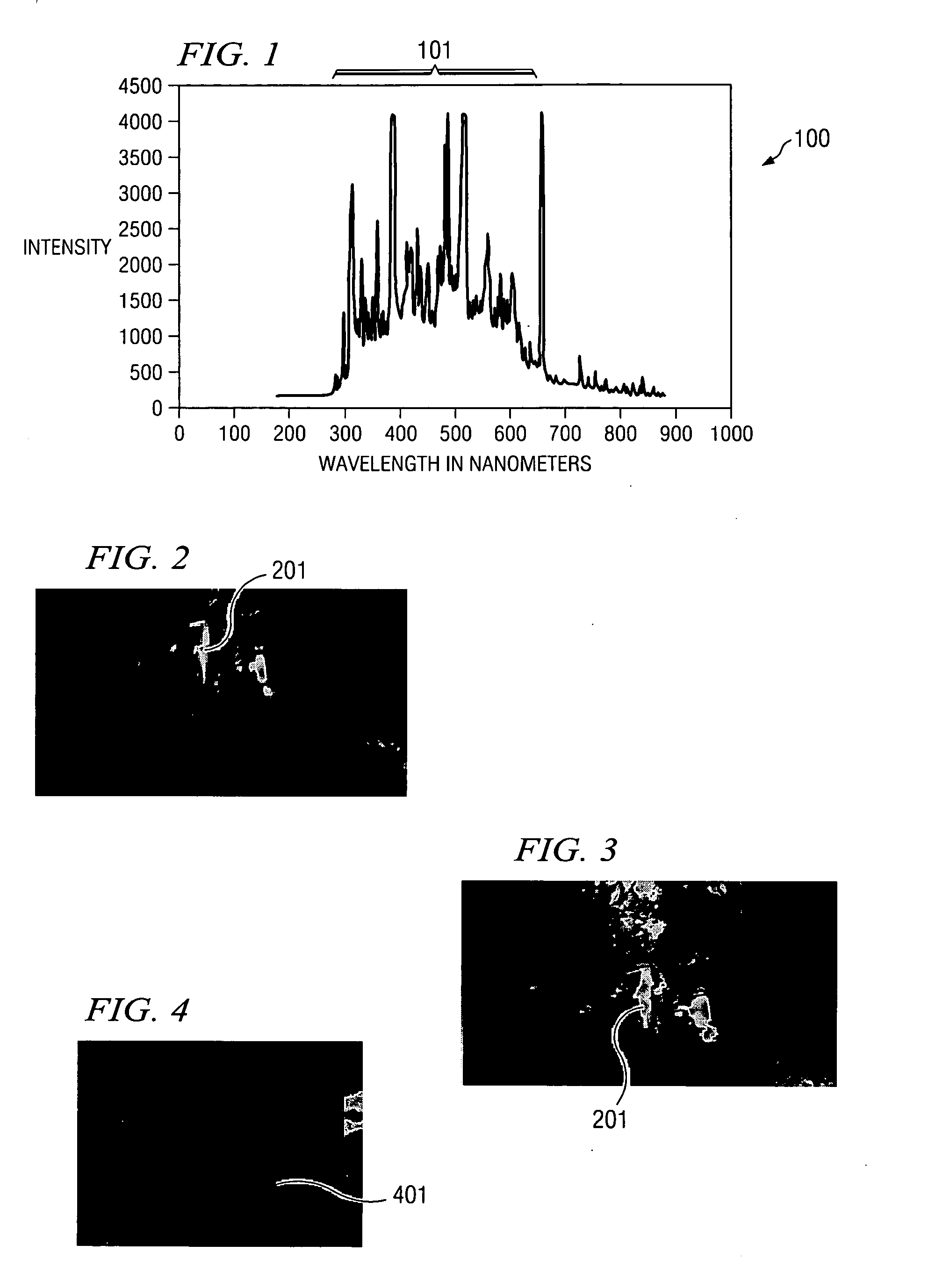
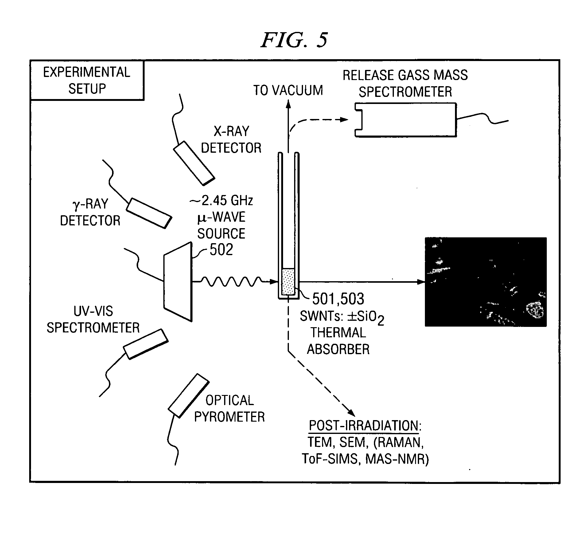
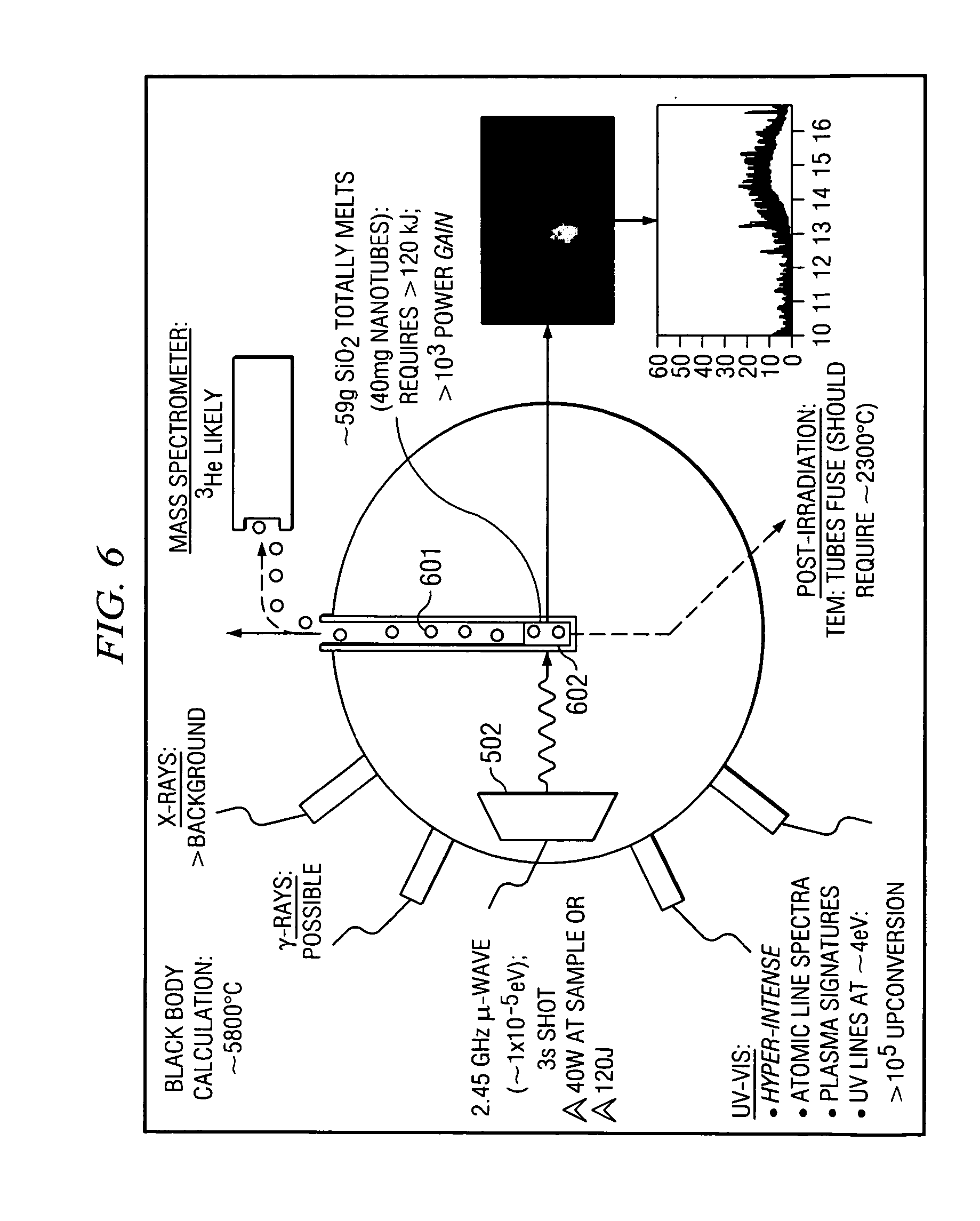
The present invention provides a process and apparatus to deliver controlled amounts of heat (thermal) energy, from low levels to very intense levels, to both microscopic and macroscopic locations in a object remotely, not necessarily involving direct contact with the object, where the energy delivered remotely is less than the energy released by the object. This could also be used as a method of converting microwave energy to thermal energy in a very efficient manner. This heat energy released from the carbon nanotubes can be in excess of the amount of energy supplied. The nanotube / microwave reaction also produces a highly ionized plasma, this being a result of much higher E fields in the near field region, which can also be accomplished with the use of resonant conditions in such devices as resonant cavities, and waveguides. This effect can be reduced in physical size to the level of several carbon nanotube ropes (microscopic) to very many nanotubes (macroscopic) effect. This effect is further aided or increased by increasing the purity of the carbon nanotube sample, increasing the density of the nanotube sample, and reducing the diameter of the nanotubes in the sample. More specifically, the present invention comprises a novel and previously unanticipated source of local thermal energy production by the exposure of carbon nanotubes by EM radiation in the radio and microwave spectral regions. The present invention comprising a process and apparatus to remotely delivering highly controlled amounts of EM to the carbon nanotubes.
The carbon nanotubes are heated as a result of their interaction with the microwaves. The technology used in generating microwaves is mature, such that microwave generators can be made portable with little difficulty. As used in the present invention, the nanotubes must be in a configuration or space that allows the E-field to be as high as possible. This can be achieved by several different methods such as, but not limited to, near field configurations, or in some resonant device such as a resonant cavity. The nanotubes can be placed in a device such as a heat engine, or a high explosive, or the nanotubes could merely be in empty space, provided in each case that there is no chance for oxidation of the nanotubes. With adequate shielding, portable microwave sources can be made safe for use in vehicles or power generator applications. If a microwave transparent container is used, advantageously, only the carbon nanotubes are heated. Conventionally available microwave transparent containers can be used in the process and apparatus of the present invention. Microwaves, when properly applied to the carbon nanotubes, cause an absorbed or adsorbed gas, such as hydrogen or oxygen, or some other gaseous material, to escape the carbon nanotubes. The released gas can then be used for energy production. The carbon nanotubes useful for this process include SWNTs and multi-wall types. However, the use of carbon nanotubes with smaller aspect ratios is preferable as the hydrogen tends to bond better with highly damaged nanotubes. Undamaged carbon nanotubes also can be used advantageously in the present invention. Moreover, low wattage microwaves, i.e. less than 100 W, can also be used to effectively heat nanotubes, thereby providing a safe level of power input and little to no degradative effect to the tube itself.

Problems solved by technology

These techniques can damage the carbon nanotubes in various ways, in many cases, making them non-reusable.
Further, conventionally used desorption techniques are very slow in rendering the adsorbed or absorbed gas for use.
As such, these techniques are not useful in fuel cell applications.

Method used


Image

  • Process and apparatus for energy storage and release
  • Process and apparatus for energy storage and release
  • Process and apparatus for energy storage and release

Examples


Embodiment Construction

The present invention comprises an improved process and apparatus for the irradiation of carbon nanotubes using EM radiation, and the utilization of the effects of the process thereof. The invention is implemented by the deposition or placement of nanotubes at specific locations in or proximate to an object or in isolation. More specifically, the present invention relates to a process and apparatus for delivering controllable amounts of heat energy, from low levels to very intense levels, to microscopic or macroscopic locations in a object remotely, not necessarily involving direct contact with the object, where the energy delivered remotely is less than the energy released from the object or for delivering controllable amounts of heat energy, from low levels to very intense levels generally. The present invention further comprises the process of obtaining a certain reaction and device or method for initiation of said reaction to provide an unexpected source of local thermal energy...


PUM


Abstract

The present invention provides a process and apparatus to store and deliver controlled amounts of heat and light energy, from low levels to very intense levels, to microscopic locations in a object remotely, not necessarily involving direct contact with the object, where the energy delivered remotely is less than the energy released by the object. More specifically, the present invention comprises a novel and previously unanticipated source of local energy production by the exposure of carbon nanotubes by EM radiation in the radio and microwave spectral regions. The present invention comprising a process and apparatus to remotely delivering highly controlled amounts of EM to the carbon nanotubes.

Description

BACKGROUND OF THE INVENTION Carbon nanotubes, discovered in 1991 by Sumio lijima, are materials consisting of multiple layers of closed carbon shells, with a graphite like chemical structure. The carbon nanotubes which have multiple interior pipes that are layered on one another are termed multi-walled carbon nanotubes (“MWNTs”). The diameters of MWNTs are typically 4-30 nanometers (“nm”) with lengths of up to 1 micrometer, with many layers, at times there being up to 100 layers. These graphite pipes are seamless. More recent discoveries into the nature of carbon nanotubes have led to the production of carbon nanotubes consisting of only one seamless pipe of carbon. These carbon nanotubes are referred to as single-walled carbon nanotubes (“SWNTs”). The diameters of SWNTs range from 0.4-3 nm while the lengths range typically from one or more micrometers to many centimeters. SWNTs are unique in that they exhibit a tensile strength stronger than steel with a density lower than aluminu...

Claims


Application Information

Patent Timeline
IPC IPC(8): H01J17/26H01M4/86H01M8/00H05B6/64
CPCB82Y10/00B82Y30/00B82Y40/00Y02E60/50H01M4/926H01M8/04208H01M8/04216C01B31/0206C01B32/15
Inventor IMHOLT, TIMOTHY JAMESALLARA, DAVIDGNADE, BRUCEROBERTS, JAMES ANDREW
Owner PENN STATE RES FOUND
Learn More