Gradient-index lens and composite optical element utilizing the same
- Summary
- Abstract
- Description
- Claims
- Application Information
AI Technical Summary
Benefits of technology
Problems solved by technology
Method used
Image
Examples
first embodiment
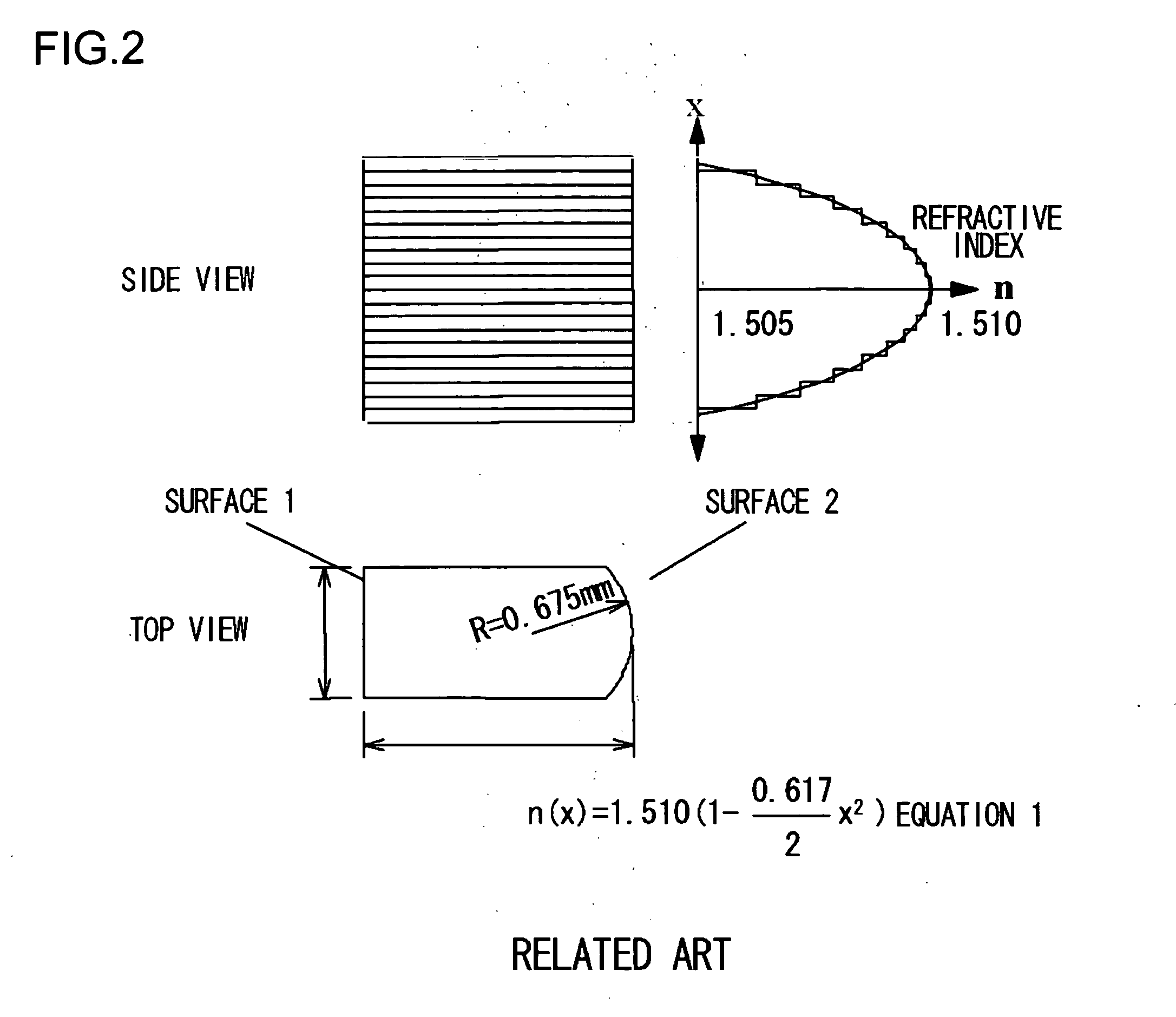
FIGS. 4A and 4B illustrate the shape and dimensions of an optical element according to a first embodiment. FIG. 5 shows a refractive index profile thereof. The refractive index is so designed as to present a profile obtained by a step approximation of Equation 1.
This optical element is produced using an organic-inorganic composite material that is synthesized through the following process.
(1) Production of a Hydrolytic Polycondensate Solution of a Metal Alkoxide
<Solution A>
Solution A is produced by mixing: 3-methacryloxypropyltriethoxysilane. (hereinafter referred to as MPTES): 13.2 grams; Ethanol: 14.2 grams; and Hydrochloric acid (2N): 1.35 grams
and then, after leaving the mixture standing at 30° C. for 45 hours, heating it in a heating furnace at 90° C. for 40 minutes to remove the ethanol (solvent).
<Solution B>
Solution B is produced by mixing: Phenyltrimethoxysilane (hereinafter referred to as PhTMS): 13.2 grams; Ethanol: 14.2 grams; and Hydrochloric ac...
second embodiment
FIGS. 7A and 7B illustrate the shape and dimensions of a gradient-index lens according to a second embodiment. FIG. 8 shows a refractive index profile thereof. The refractive indices are so designed as to present a profile obtained by a step approximation of Equation 2-1 in the middle part of the lens and a profile obtained thereby of Equation 2-2 in the peripheral part of the lens.
In the second embodiment, the same material used as in the first embodiment was used and the thickness of each layer was as follows.
From the first layer through the fourth layer as well as from the seventeenth layer through the twentieth layer: 11 μm.
The fifth layer and the sixteenth layer: 10 μm.
The sixth layer and the fifteenth layer: 16 μm.
When the HeNe laser was irradiated, in a manner similar to the first embodiment, to the gradient-index lens thus prepared in the second embodiment, the light beams were focused on the surface 1, too. FIG. 9 shows the light intensity distribution of focusing...
third embodiment
FIGS. 10A and 10B illustrate a shape of gradient-index lens according to a third embodiment. Referring to FIG. 10B showing a top view of the gradient-index lens, the curvature of surface 2 is 0.697 and the outside dimensions are the same as those in the first embodiment above, namely, the horizontal length is 2 mm and the vertical length is 1 mm. FIG. 11 illustrates a refractive index profile. In the case of FIG. 11, an element is so designed that the refractive index in the middle part of the element is distributed in a manner expressed by Equation 3-1 and the refractive index in the periphery thereof is distributed by performing the step approximation on Equation 3-2. The thickness of each layer is the same as that in the second embodiment.
In the third embodiment, quartz film is stacked using a CVD method, and Ge is added during the film formation in a manner such that each layer has a desired refractive index, so as to produce a gradient-index lens. The relationship between the...
PUM
| Property | Measurement | Unit |
|---|---|---|
| Thickness | aaaaa | aaaaa |
| Length | aaaaa | aaaaa |
| Area | aaaaa | aaaaa |
Abstract
Description
Claims
Application Information
 - R&D
- Intellectual Property
- Life Sciences
- Materials
- Tech Scout
- Unparalleled Data Quality
- Higher Quality Content
- 60% Fewer Hallucinations
Browse by: Latest US Patents, China's latest patents, Technical Efficacy Thesaurus, Application Domain, Technology Topic, Popular Technical Reports.
© 2025 PatSnap. All rights reserved.Legal|Privacy policy|Modern Slavery Act Transparency Statement|Sitemap|About US| Contact US: help@patsnap.com


