Optical lens and information recording and reproducig device

a technology of information recording and reproducing device, which is applied in the field of optical lenses, can solve the problems of reducing the transmission light amount of the total lens, affecting the transmission of light, so as to achieve the effect of increasing the amount of transmitted ligh

Inactive Publication Date: 2005-01-13
KONICA MINOLTA OPTO
View PDF4 Cites 21 Cited by
  • Summary
  • Abstract
  • Description
  • Claims
  • Application Information

AI Technical Summary

Benefits of technology

[0019] In the structure described in Item 1, the reflectance within a range from wavelength λ1 to wavelength λ2 is 4% or less on the central portion where an angle of incidence of light is small among the first lens surface. Therefore, the wavelength that makes the reflectance to be minimum (hereinafter referred to as reflection minimum wavelength) is longer than the wavelength λ1. Since the wavelength λ1 is in a range of 348-460 nm in this case, the reflection minimum wavelength tends to be longer than wavelength 390-420 nm of the first laser light source. On the other hand, in the outer peripheral portion occupying a large area in the first lens surface, the reflectance is minimum for the wavelength shorter than the reflection minimum wavelength, namely, for the wavelength close to wavelength of the first laser light source, becau

Problems solved by technology

Therefore, in the objective lens on which the conventional antireflection coating is provided, the reflectance for a laser beam at the outer peripheral portion is higher though the reflectance for a laser beam at the central portion is low, thus, an amount of light transmitted through the outer peripheral portion becomes smaller relatively than an amount of light transmitted through the central portion, resulting in problems of deterioration of spectral intensity of transmitted light of the total lens, an increase in a beam spot diameter caused by a fall of light-converging functions and of a decline of an amount of beams.
However, in the objective lens having high NA, an angle of incidence of light on an outer peripheral portion of the lens is extremely large, because a curvature of the lens surface is great.
Therefore, an amount of light transmitted through the outer peripheral portion has been lowered sharply, resulting in problems that an increase in a spot diameter cannot be controlled, and realizing of a large capacity of an optical recording medium is disturbed.
However, when increasing simply an amount o

Method used


Image

  • Optical lens and information recording and reproducig device
  • Optical lens and information recording and reproducig device
  • Optical lens and information recording and reproducig device

Examples


examples

[0189] The invention will be explained specifically as follows, referring to the examples to which, however, the invention is not limited.

[0190] 1. Lens in First Embodiment

[0191] (Evaluation of Transmittance of Lens and Spot Forms)

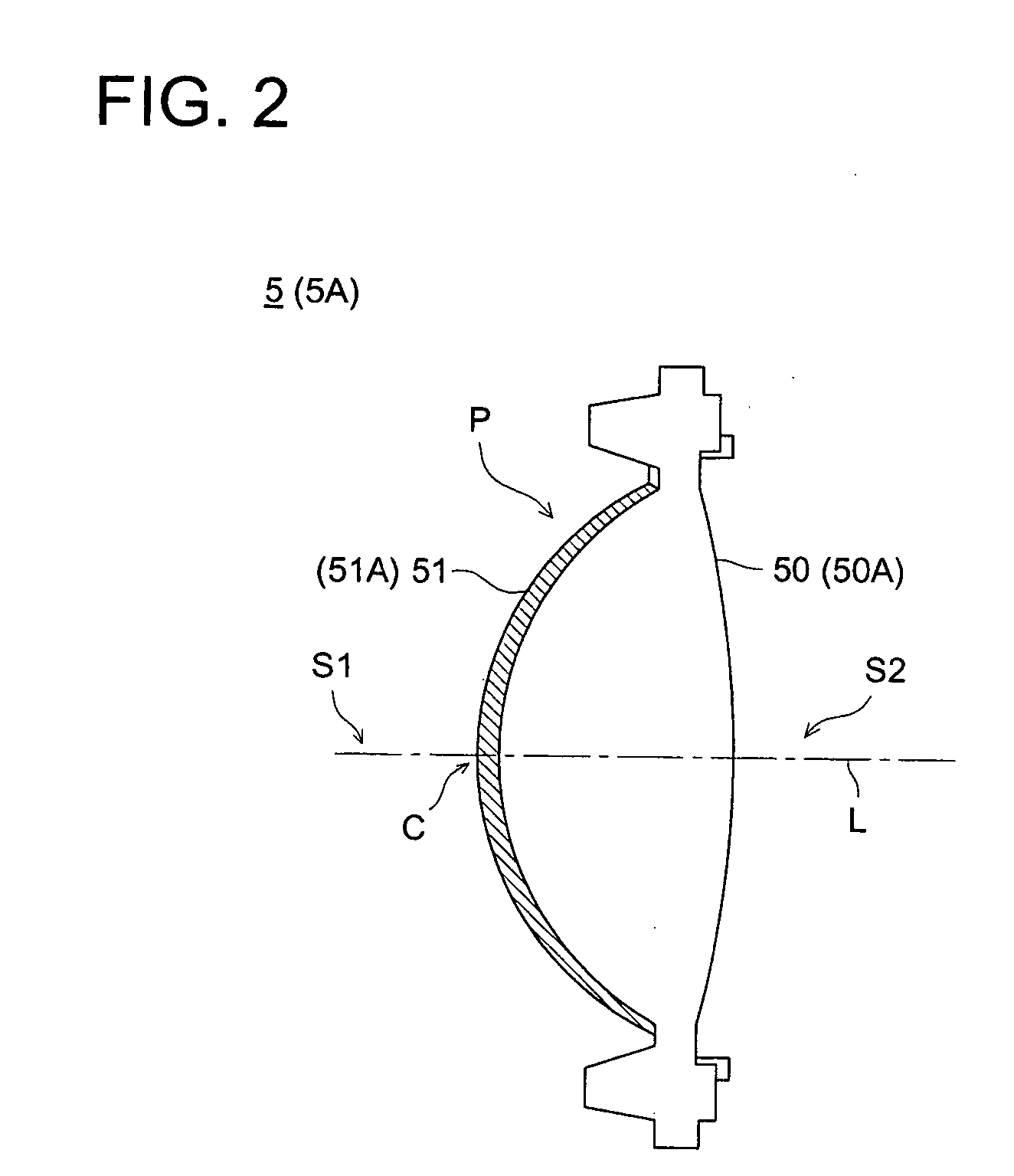
[0192] As objective lens 5 in the aforesaid First Embodiment, there were formed ones wherein antireflection coatings 51 having respectively layer structures shown in Table 1 are provided respectively on lens surfaces S1 and S2.

[0193] Incidentally, the numerical aperture of the objective lens 5 was made to be 0.6. The maximum value of surface angle θ of the lens surface S1 was made to be 53°. “OA-600” (trade name, made by Optron Inc.) in the drawing is a mixture of tantalum oxide and titanium oxide. Each antireflection coating 51 will be specified by the number shown on the uppermost column in the drawing in the explanation below.

TABLE 1No.12345678λ1Layer No.290310320335348360375380Material1MgF266.970.474.077.681.284.888.492.02OA60085.090.595.911.2108...

examples 3-5

[0258] 3. Lens in Third Embodiment (1)

[0259] (Evaluation of Transmittance of Lens and Spot Forms)

[0260] As objective lens 5B in the aforesaid Third Embodiment, there were formed ones wherein antireflection coatings 51B of No. 4″ shown in Table 8 are provided respectively on lens surfaces S1 and S2 of lens main body 500, and antireflection coatings 51B having respectively layer structures shown in Table 5 are provided respectively on lens surfaces S3 and S4 of lens main body 501. In this case, spectral reflection characteristics of each antireflection coating 51B shown in Table 8 are shown in FIG. 15. Incidentally, this diagram illustrates the aforesaid wavelength λ1 and wavelength λ2 about antireflection coating 51B of No. 2″.

TABLE 8No.1″2″3″4″5″6″7″8″λ13503603703754004404584801SiO291.694.3111.7112.2105.3118.2122.2128.02OA60032.032.925.426.036.941.643.045.13SiO237.538.446.447.443.148.450.052.34OA60018.919.422.824.921.824.525.426.65SiO216.617.114.6175.919.121.522.223.2λ2730740770...


PUM

PropertyMeasurementUnit
Fractionaaaaaaaaaa
Angleaaaaaaaaaa
Angleaaaaaaaaaa

Abstract

An optical lens to be arranged in an optical information recording and/or reproducing apparatus includes at least one lens main body; an antireflective film arranged on a first lens surface which has the largest surface angle θ on an outer peripheral portion in an effective radius of lens surfaces on the lens main body; wherein for a light entering perpendicularly to a central portion of the first lens surface whose central portion has a surface angle θ of 0 degree, a spectral reflectance of the antireflective film has one or more regions in which the spectral reflectance is continuously 4% or below and the wavelength includes at least a part of a wavelength region of 300 to 1000 nm, the broadest wavelength region of the one or more wavelength regions extends from wavelength λ1 to λ2 and the wavelength λ1 is in a range of 348-460 nm.

Description

BACKGROUND OF THE INVENTION [0001] The present invention relates to an optical lens to be provided on an information recording and reproducing device capable of conducting at least one of recording of information on an optical recording medium and reproducing of information recorded on an optical recording medium, and to an information recording and reproducing device equipped with the optical lens. [0002] There has been available an optical pickup device (an information recording and reproducing device) as a device to conduct recording of information on an optical recording medium and reproducing of information recorded on an optical recording medium. The optical pickup device is one that converges a ray of light emitted from a semiconductor laser light source on an information recording surface of an optical recording medium with an objective lens (optical lens), and thereby conducts recording and reproducing of information. [0003] On this objective lens, there is provided an anti...

Claims


Application Information

Patent Timeline
IPC IPC(8): G02B1/11G02B1/10G02B3/00G02B13/00G11B7/00G11B7/125G11B7/1275G11B7/135G11B7/1374G11B7/1392
CPCG11B7/1275G11B2007/0006G11B7/13922G11B7/1374
Inventor OHTA, TSTSUOTAKA, KUNIHIKO
Owner KONICA MINOLTA OPTO
Why Eureka
Try Eureka