Low thermal inerta scanning adiabatic calorimeter

a calorimeter and scanning adiabatic technology, applied in the direction of instruments, heat measurement, material heat development, etc., can solve the problem of limited advantages of using the method on older machines

Active Publication Date: 2005-01-13
NETZSCH GERATEBAU GMBH
View PDF10 Cites 34 Cited by
  • Summary
  • Abstract
  • Description
  • Claims
  • Application Information

AI Technical Summary

Problems solved by technology

In some cases, existing equipment can be modified to allow use of the new techniques, although the advantages of...

Method used


Image

  • Low thermal inerta scanning adiabatic calorimeter
  • Low thermal inerta scanning adiabatic calorimeter
  • Low thermal inerta scanning adiabatic calorimeter

Examples


Embodiment Construction

The invention comprises both an improved calorimeter, and improved measurements and measurement techniques that are made possible by the improved calorimeter.

1. The Calorimeter

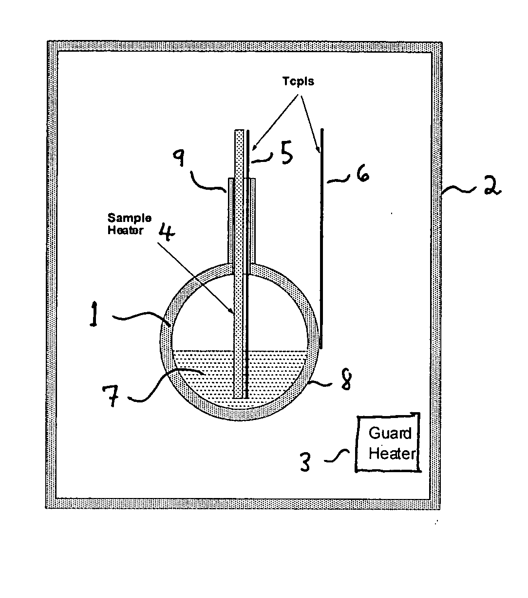
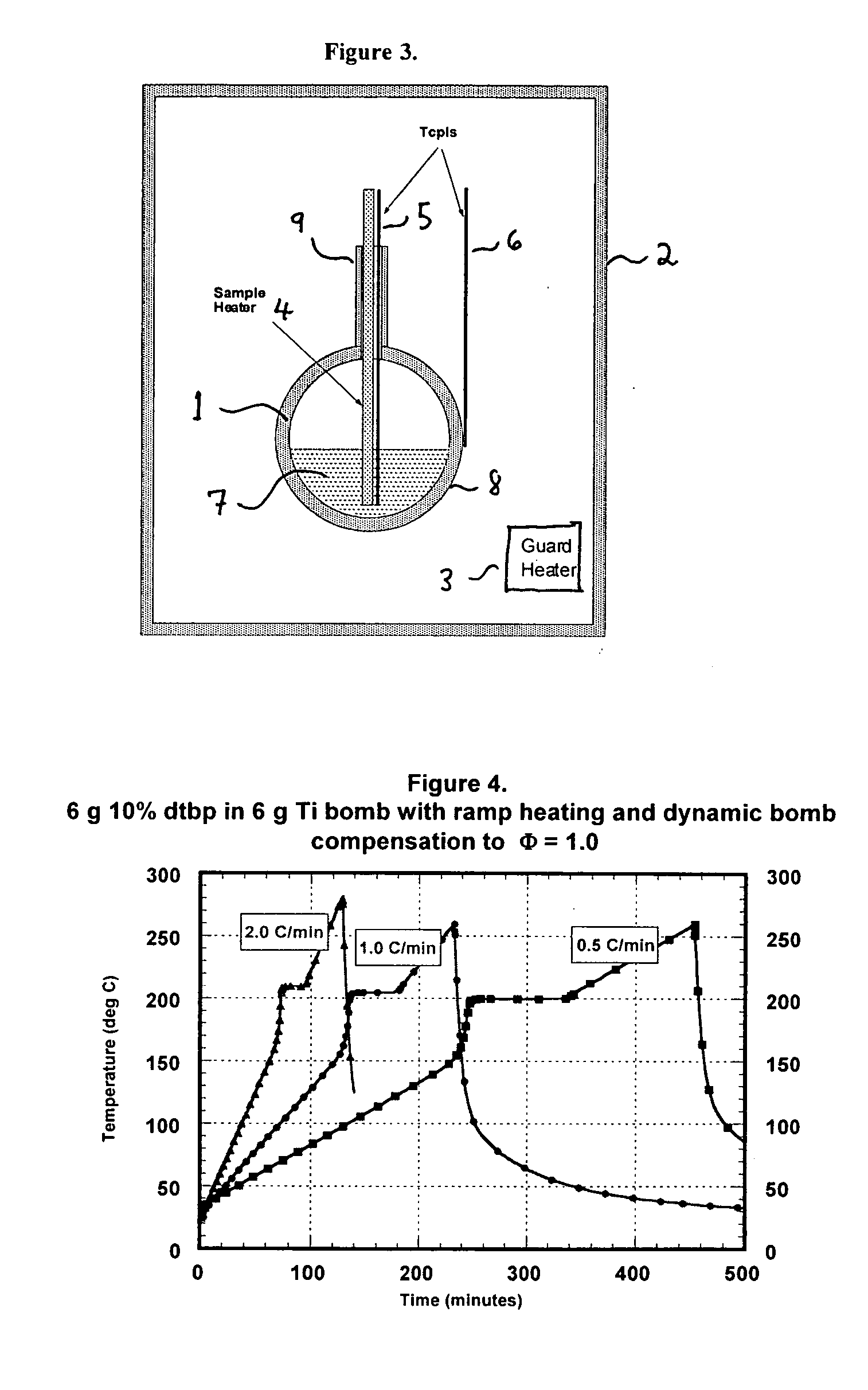
The calorimeter is shown schematically in FIG. 3. The calorimeter comprises a sample reaction vessel or bomb 1, an enclosure 2, guard heaters 3 connected to enclosure 2, sample heater 4, first (outer bomb) thermocouple 6, optional second (sample) thermocouple 5, sample 7, and outer surface 8 of the bomb 1. Each of the guard heaters 3, of which there are typically one to four, has an associated thermocouple (not shown). Each of the several thermocouples provides data to a controller (not illustrated). The controller regulates the amount of heat provided by the sample heater 4 and each guard heater 3. The controller also records the data from the thermocouples and performs calculations to select the amount of power to be provided to the sample heater 4 and the guard heaters 3.

The guard heaters 3 are typica...


PUM


Abstract

A new adiabatic scanning calorimeter allows the thermal mass of a high-pressure reaction vessel to be dynamically compensated during a test. This allows the effective Φ factor for the experiment to be reduced to 1.0 without the use of complex pressure balancing equipment. Endothermic events can be quantified and sample specific heats can be measured. The time required for test completion is much shorter than for conventional adiabatic calorimeters, thus considerably improving apparatus productivity. The sensitivity to exotherm detection is at least as good as existing adiabatic calorimeters employing the Heat-Wait-Search strategy, but does depend on the temperature-scanning rate. In addition, the heat of reaction is obtained without reference to the heat capacity of the sample, pressure is measured continuously, reactants may be injected into the test vessel and the sample can be mixed during the test.

Description

Thermal stability of materials, exothermic reactions, and thermal runaway are very often studied in the Accelerating Rate Calorimeter, more often referred to as the ARC® Scientists at Dow Chemical first developed this device in the late 1970s and many papers describing the use of the ARC have since been written (1,2,3). Using this apparatus, a sample and a sample bomb are heated to a temperature where exothermic activity is detected in the sample by observation of the rate of temperature change of the sample. The sample and bomb are prevented from losing heat to the environment by careful control of guard heaters surrounding the sample bomb. A heating algorithm, commonly referred to as the Heat-Wait-Search™ (HWS) strategy, is used to control the initial heating of the sample and to bring the sample to a stable temperature during the exotherm search period. FIG. 1 illustrates the HWS strategy and the use of the new, TIAX manufactured ARC to obtain heat of decomposition and reaction ...

Claims


Application Information

Patent Timeline
IPC IPC(8): G01K17/00G01N25/26G01N25/48
CPCG01K17/00G01K17/04G01N25/4846G01N25/4833G01N25/26G01K7/02G01K7/22G01K13/12G01N25/20
Inventor CHIPPETT, SIMON
Owner NETZSCH GERATEBAU GMBH
Why Eureka
Try Eureka