Hydrostatic bearing, alignment apparatus, exposure apparatus, and device manufacturing method

Inactive Publication Date: 2005-01-13
CANON KK
View PDF19 Cites 25 Cited by
  • Summary
  • Abstract
  • Description
  • Claims
  • Application Information

AI Technical Summary

Benefits of technology

[0005] The present invention has been made in consideration of the above-mentioned problems, and has as its object to provide a technique

Problems solved by technology

However, in supply pressure control for the hydrostatic bearings in the conventional technique, the following problem remains unsolved.
Consequently, a little clearance of the hydrostatic bearing cannot be ensured.
At whatever high speed the supply pressure of the

Method used


Image

  • Hydrostatic bearing, alignment apparatus, exposure apparatus, and device manufacturing method
  • Hydrostatic bearing, alignment apparatus, exposure apparatus, and device manufacturing method
  • Hydrostatic bearing, alignment apparatus, exposure apparatus, and device manufacturing method

Examples


first embodiment

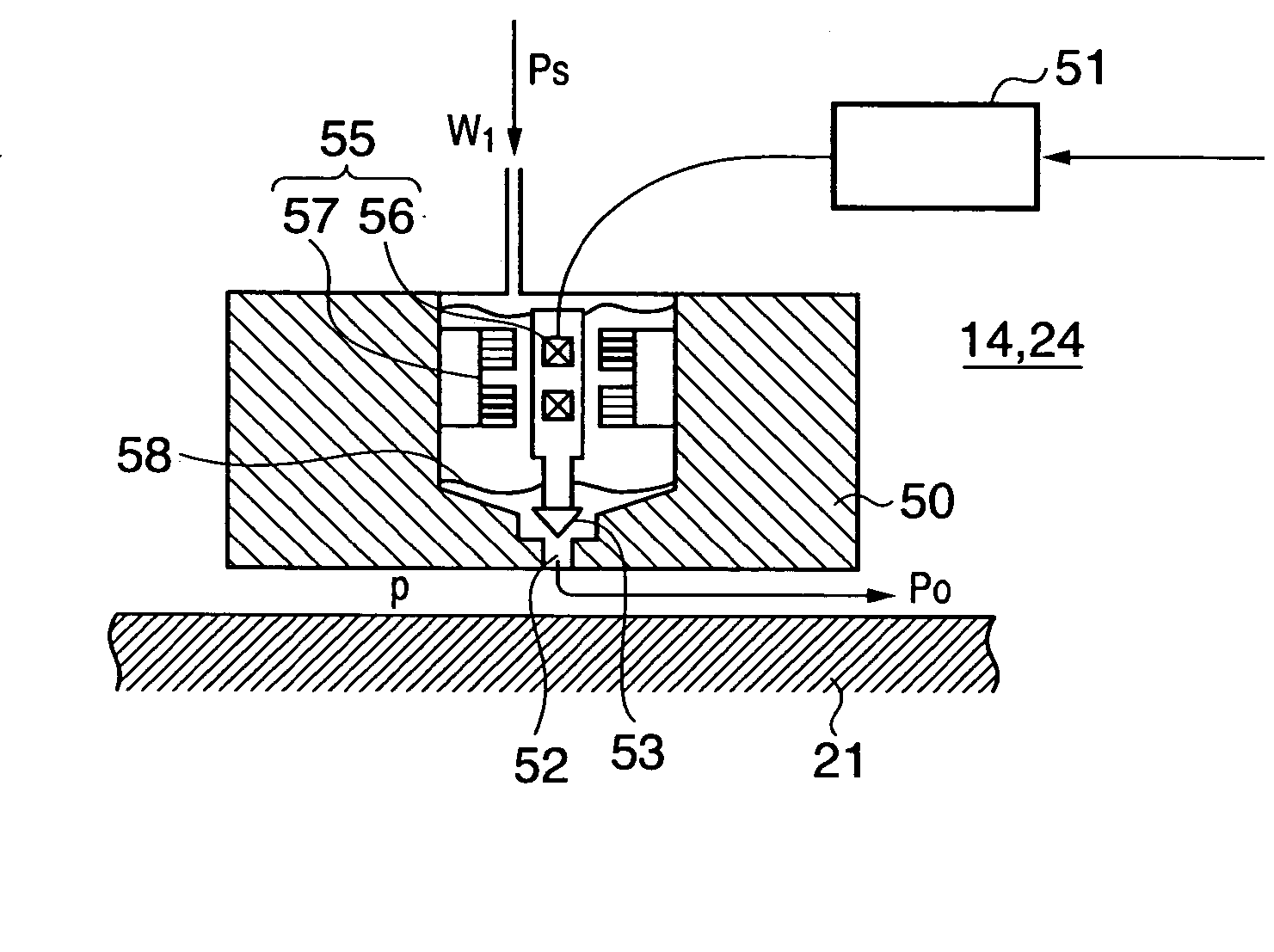
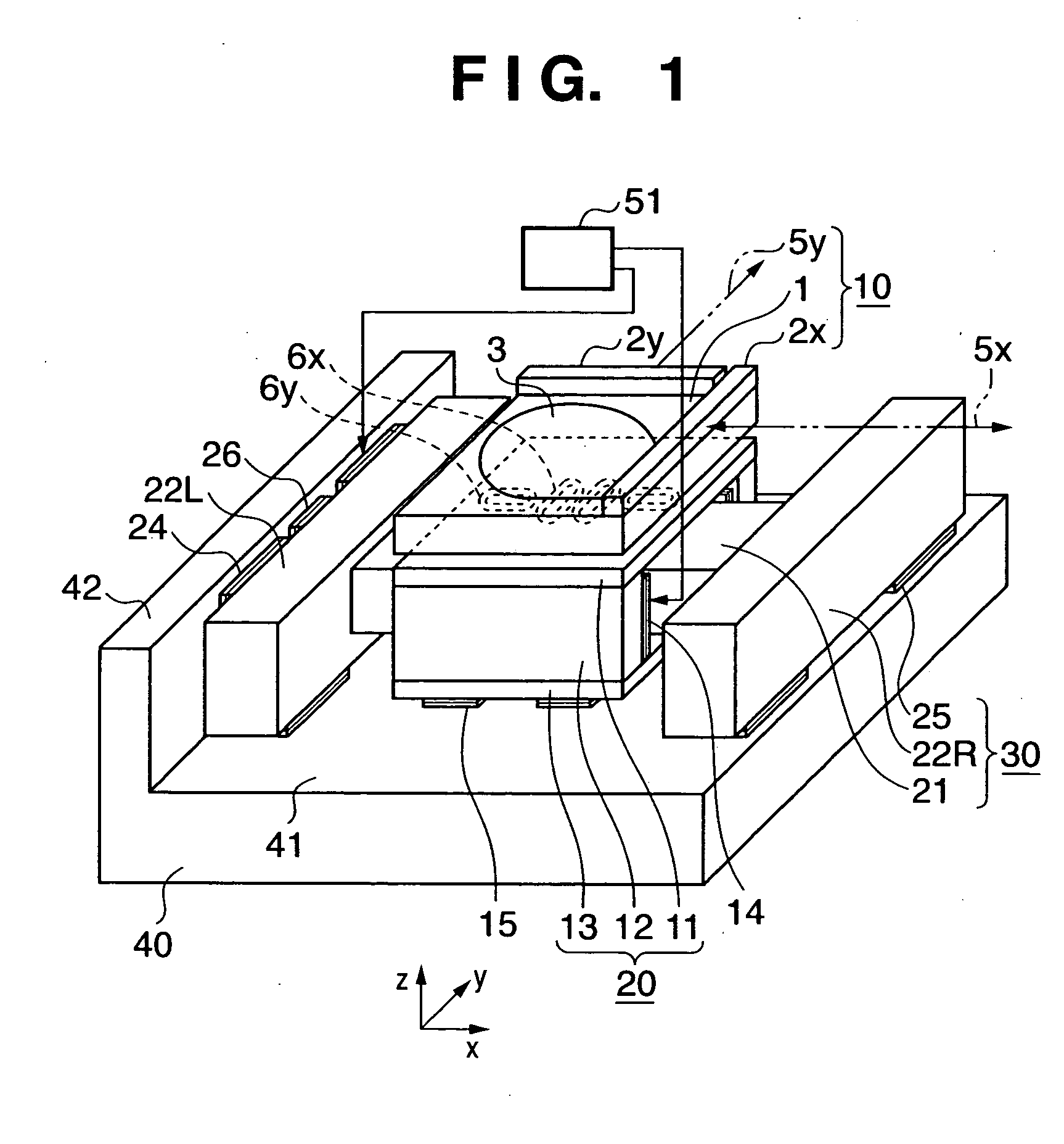
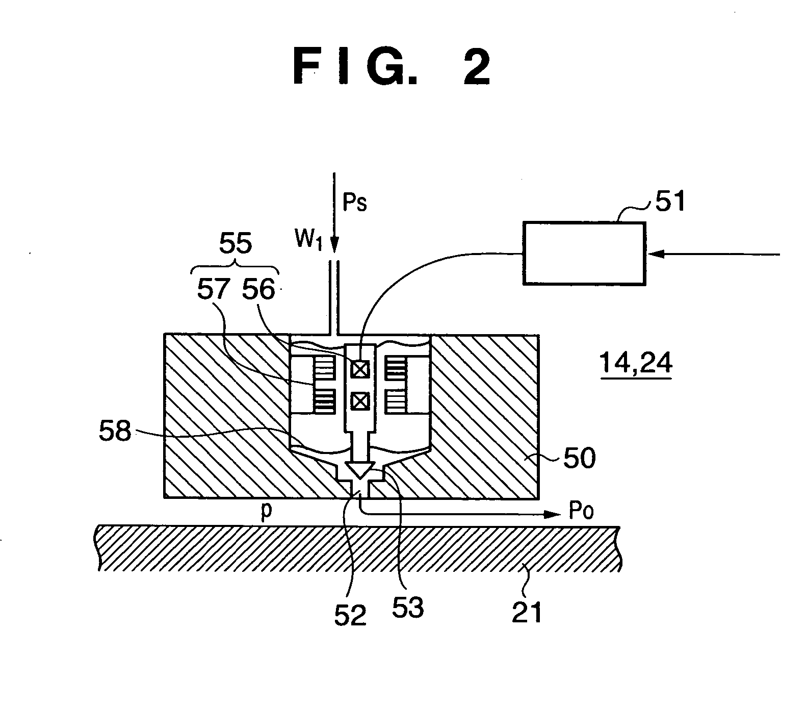
[0061] [First Embodiment]

[0062]FIG. 1 shows an arrangement example of an alignment apparatus according to the first embodiment of the present invention. An alignment apparatus to be illustrated in this embodiment is mounted on various measuring instruments or processing machines, a projection exposure apparatus for use in a semiconductor lithography process, or the like. The alignment apparatus moves and aligns a substrate such as a wafer or an original such as a reticle at high speed and high precision.

[0063] The alignment apparatus comprises a wafer stage 10, X stage 20, Y stage 30, and fixed base 40. The wafer stage 10 also has a wafer 3, X-Y position measurement mirrors 2x and 2y, and a top plate 1 which holds them. The X-Y position measurement mirrors 2x and 2y have respective reflection surfaces which are irradiated with laser beams 5x and 5y. Measuring the laser beams reflected by the reflection surfaces using interferometers makes it possible to accurately measure an X-Y di...

second embodiment

[0081] [Second Embodiment]

[0082]FIG. 5 is a sectional view, taken along the X-Y plane, showing the detailed arrangement of X side hydrostatic bearings according to the second embodiment.

[0083] In the first embodiment, each hydrostatic bearing having an instantaneous pressure increase / decrease function operates constantly. However, conventional hydrostatic bearings 14′ which operate constantly and hydrostatic bearings 14 (24) having instantaneous pressure increase / decrease functions can be juxtaposed to each other, as shown in FIG. 5. When a driving force does not act on an X stage 20 serving as a movable member (when the X stage 20 is in a stationary state or when the X stage 20 is moving at a constant speed), the internal pressure of the hydrostatic bearings 14 (24) having the instantaneous pressure increase / decrease functions is reduced to substantially zero, and the X stage 20 is supported by only the conventional hydrostatic bearings 14′. Only when a driving force acts, the hyd...

third embodiment

[0085] [Third Embodiment]

[0086] A case will be described with reference to FIGS. 6 and 7 wherein an alignment apparatus according to this embodiment is used in a vacuum atmosphere. FIG. 6 shows the case wherein the alignment apparatus is used in the vacuum atmosphere. Also, in FIG. 6, a stage different from that in the first embodiment is shown.

[0087] The stage serving as the alignment apparatus is arranged in a chamber 100 whose interior is kept in a vacuum state. The stage comprises a center slider 120 which can move in the X-Y plane, an X slider 130x which can move only in the X direction, and a Y slider 130y which can move only in the Y direction. The X slider 130x is supported in the Y and Z directions by a pair of hydrostatic bearings 124x. The Y slider 130y is supported in the X and Z directions by a pair of hydrostatic bearings 124y. The center slider 120 is supported with respect to the X slider 130x and Y slider side surfaces 121x and 121y through hydrostatic bearings 114...


PUM


Abstract

A bearing surface (50) opposing a movable guide (21) of a hydrostatic bearing has a gas supply hole (52) which has an orifice with a diameter smaller than that of the outer shape of the bearing. Each of hydrostatic bearings (14, 24) incorporates a poppet valve (53) which can seamlessly change the flow resistance in the gas supply hole (52), an actuator unit (55) for linearly driving the poppet valve (53), and a guide mechanism (58) which guides the poppet valve (53) so as to set the poppet valve (53) in linear motion. The actuator unit (55) has, for example, coils (56) arranged on the movable side (the base of the poppet valve (53)) and permanent magnets arranged on the fixed side (a portion opposing the base of the poppet valve (53)). With this arrangement, the poppet valve (53) can be driven at high speed and high precision. The poppet valve (53) is driven in accordance with a command from a controller (51). A pressure (Ps) is applied to the poppet valve (53) as the back pressure. The pressure (Ps) is restricted by the poppet valve (53) and a bearing clearance and becomes a bearing mean pressure (p).

Description

FIELD OF THE INVENTION [0001] The present invention relates to an alignment apparatus which moves and aligns a substrate such as a wafer or an original such as a reticle at high speed and high precision in, for example, various measuring instruments or processing machines, a projection exposure apparatus for use in a semiconductor lithography process, or the like and, more particularly, to an alignment apparatus suitable for use in a vacuum atmosphere. BACKGROUND OF THE INVENTION [0002]FIG. 13 shows the arrangement of a conventional alignment apparatus using a hydrostatic pressure bearing pad which moves and aligns a substrate such as a wafer (e.g., see Japanese Patent Laid-Open No. 62-24929). Reference numeral 240 denotes a fixed base 240; and 242x and 242y, X fixed guides and Y fixed guides which extend and are fixedly provided in the X and Y directions. Reference numerals 230x and 230y denote an X movable guide and Y movable guide which intersect each other and are arranged in a ...

Claims


Application Information

Patent Timeline
IPC IPC(8): B23Q1/30F16C29/02F16C32/06G03F7/20H01J37/20H01J37/305H01L21/027H01L21/68
CPCF16C29/025F16C32/0644H01L21/682G03F7/70816G03F7/70716
Inventor AKUTSU, KOTAROSAI, CHOSHOKU
Owner CANON KK
Why Eureka
Try Eureka